Protocol Is Not the Same as Cable
| System term | What it describes | What procurement must still define |
|---|---|---|
| RS-485 | Balanced electrical interface for multipoint digital communication | Pair construction, impedance required by the system, capacitance, conductor size, shielding, velocity, attenuation, length, termination and environment |
| Modbus RTU over serial line | Application and serial-line communication rules; the Modbus Organization notes that a two-wire RS-485 interface is the most common physical option | Device-specific baud rate, topology, cable, grounding, termination, biasing and maximum segment design |
| BACnet MS/TP | BACnet data link operating over an RS-485 physical layer | Approved MS/TP cable, segment length, device loading, baud rate, topology, termination and router placement |
| KNX TP | KNX system using twisted pair for communication and bus power | Registered/certified or project-approved KNX TP cable, pair allocation, installation rules, fire class and route |
| BACnet/IP or BMS Ethernet | IP-based BMS communication over Ethernet | Category cable or optical fibre, channel performance, PoE if used, redundancy, switches, cybersecurity and fire class |
This distinction prevents a common error: buying any screened twisted pair because the datasheet says “RS-485,” even though its impedance, capacitance, conductor resistance, sheath, or certification does not match the equipment or project.
1. Map the BMS Architecture Before Selecting Cable
Divide the system into layers:

- Management layer: servers, operator workstations, analytics and integration platforms
- Automation layer: supervisory controllers, BMS routers and plant controllers
- Fieldbus layer: BACnet MS/TP, Modbus RTU, KNX TP or proprietary buses
- Field-device layer: sensors, actuators, meters, VFDs, valves and equipment interfaces
For each connection, record protocol, data rate, node count, segment length, environment, power arrangement and redundancy requirement. This exposes where fieldbus cable, KNX cable, Cat6/Cat6A, fibre, control cable, or composite cable is actually needed.
Mission-critical sites should also identify which BMS functions are operationally essential. Monitoring may be redundant without the fieldbus itself being duplicated. Conversely, a single RS-485 trunk connecting all cooling equipment can become a large failure domain. Network segmentation, routers, spare capacity, and diverse pathways should be planned with the controls engineer—not assumed from the cable alone.
2. RS-485 Cable: Match the Electrical Channel
An RS-485 label is not sufficient. Request the electrical values needed by the device and protocol design:

- Balanced twisted pair
- Nominal characteristic impedance required by the system
- Conductor size and DC resistance
- Pair-to-pair and conductor-to-conductor capacitance
- Capacitance unbalance, where specified
- Attenuation at relevant frequencies
- Shield type and coverage
- Drain wire construction
- Maximum operating voltage and temperature
- Velocity of propagation where timing is important
- Overall diameter and bend radius
Many RS-485 systems use cable with a nominal impedance around 120 ohms, but the project must follow the controller and equipment manufacturer. Do not convert “commonly used” into a universal requirement.
Longer distance, higher data rate, higher capacitance, poor termination, excessive stubs, or incorrect topology can reduce communication margin. Cable selection and network design must therefore be reviewed together.
3. Modbus RTU: Treat the Bus as a System
The Modbus Organization's serial-line guide describes Modbus over serial line and notes that the RS-485 two-wire interface is the most common physical implementation, with four-wire RS-485 available as an option.
For a reliable Modbus RTU segment, confirm:
- Two-wire or four-wire interface
- Data pair and signal-common arrangement
- Device count and transceiver loading
- Bus topology and permitted stub length
- Termination at the intended ends
- Biasing provided by the approved devices
- Shield bonding and grounding method
- Baud rate and maximum segment length
- Isolation and surge protection
- Router or repeater locations
Avoid star-wiring a bus unless the equipment manufacturer explicitly supports it or approved active hubs are used. Do not connect shield drains randomly at multiple points; follow the engineered grounding plan.
4. BACnet MS/TP: Segment for Performance and Maintenance
BACnet MS/TP uses an RS-485 physical layer and token-passing communication. BACnet International guidance emphasizes that device population, router placement, network settings, future expansion, and fault isolation affect performance.
For mission-critical facilities:
- Use the cable type approved by the controller manufacturers
- Keep network segments manageable
- Reserve addresses and capacity for future equipment
- Use routers to limit the impact of one faulty field segment
- Document MAC addresses, baud rate, termination and polarity
- Avoid mixing incompatible reference-ground practices
- Commission with waveform, bias and communication diagnostics where needed
A larger theoretical device limit does not automatically mean every device should share one trunk. Smaller, well-documented segments can simplify maintenance and reduce the number of systems affected by a single wiring fault.
5. KNX TP: Verify Cable Registration and Project Acceptance
KNX TP carries communication and bus power on a twisted-pair medium. KNX Association provides a formal process for registration of twisted-pair cable. The process requires a manufacturer declaration and test results against the cable features in the KNX Specifications.

For procurement, confirm:
- Whether the tender requires registered or certified KNX TP cable
- Manufacturer and exact registered product code
- Number of pairs and permitted use of spare pairs
- Conductor size and resistance
- Cable electrical properties
- Sheath material and installation environment
- CPR class or other fire requirements
- Indoor, outdoor, UV, conduit and tray suitability
- Printing and traceability
Do not market a generic control cable as “KNX certified” unless the exact cable is covered by the applicable KNX registration or certification evidence.
6. Decide When Shielding Is Needed
Data centers and industrial facilities contain strong potential sources of electromagnetic interference:

- Variable-frequency drives
- Motors and pumps
- UPS and battery systems
- Generators and switchgear
- Transformers and busways
- High-current power circuits
- Radio systems
Shielded cable can improve noise immunity when required by the system and installed correctly. But shielding is not a substitute for pair balance, route separation, correct termination, or good grounding.
Specify:
- Overall foil, braid, or combined screen
- Coverage and drain wire
- Screen continuity through junctions
- Bonding location and method
- Equipment reference-ground arrangement
- Separation from power circuits
- Rules at panel entries and field devices
An ungrounded or incorrectly grounded screen may add cost without delivering the expected EMC benefit.
7. Fire Performance and Sheath Selection
Mission-critical does not automatically mean every BMS cable must be fire resistant. The project fire strategy should distinguish:
- Normal BMS monitoring circuits
- Circuits that interface with life-safety systems
- Circuits required to operate during fire
- Cables installed in escape routes, plenums, risers or fire-rated zones
- Cables subject to CPR or local reaction-to-fire requirements
Possible requirements include PVC, LSZH, flame-retardant performance, CPR Euroclass, plenum/riser listing, or circuit integrity. These properties are different and should be written separately.
Where BMS interfaces with fire alarm, smoke control or emergency shutdown, the controls and fire consultants should define whether a fire-survival cable or protected pathway is required. Do not infer circuit-survivability requirements from the word “BMS.”
8. Choose the Right Backbone Media
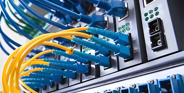
RS-485 and KNX are usually field-level media. Larger campuses often aggregate BMS traffic over Ethernet and fibre.
Use structured copper where the channel length, environment, bandwidth and grounding conditions fit. Consider optical fibre for:
- Inter-building links
- Long distances
- High electromagnetic interference
- Electrical isolation between buildings or plant areas
- Redundant campus rings or diverse backbone paths
- Higher bandwidth and future expansion
The BMS architecture should identify where protocol conversion occurs and how controller, router, switch and fibre-transceiver failures are handled.
9. Installation and Commissioning Checklist
Installation
- Maintain correct bus topology
- Keep stubs within equipment limits
- Install termination only at intended locations
- Preserve pair twist close to terminals
- Maintain cable separation
- Follow bend-radius and pulling-tension limits
- Keep screen and drain continuity
- Label both ends and intermediate panels
- Record route, segment and device identifiers
- Firestop penetrations with approved systems
Commissioning
- Verify conductor continuity and polarity
- Measure insulation and loop resistance as applicable
- Confirm termination resistance with power isolated where appropriate
- Check bias voltage and reference ground
- Confirm baud rates, addresses and device settings
- Review error counters and retries
- Test worst-case segment operation
- Save controller and router configuration
- Produce as-built topology and cable schedule
Common Selection Errors
- Buying “RS-485 cable” without electrical parameters
- Treating Modbus, BACnet and KNX as the same physical system
- Using star topology on an unsupported serial bus
- Adding shielding without a bonding plan
- Running fieldbus cable beside high-current power for convenience
- Using one very large MS/TP segment instead of planned fault domains
- Calling a generic cable KNX certified without traceable evidence
- Treating LSZH as circuit integrity
- Ignoring conductor resistance and voltage drop on powered buses
- Omitting backbone fibre and surge/isolation planning between buildings
How ZION Can Support the Project
ZION can match screened and unscreened control cable, RS-485 cable, KNX-oriented cable, structured copper, indoor/outdoor fibre, patch panels and connectivity accessories to an approved BMS cable schedule. Final claims for protocol approval, KNX registration, fire performance or certification must be tied to the exact offered ZION product and evidence.
Related ZION Resources
Use this ZION resource when the project needs a matching product family or supporting cable selection context.
Use this ZION resource when the project needs a matching product family or supporting cable selection context.
Use this ZION resource when the project needs a matching product family or supporting cable selection context.
Use this ZION resource when the project needs a matching product family or supporting cable selection context.
FAQ
Is every screened twisted pair suitable for RS-485?
No. The project should confirm impedance, capacitance, conductor resistance, shielding, topology, length, termination, grounding and device-manufacturer requirements.
Can Modbus, BACnet MS/TP and KNX use the same cable?
Not automatically. Modbus RTU and BACnet MS/TP can use RS-485 physical layers, while KNX TP is a distinct twisted-pair system with its own project acceptance and registration expectations.
When should a BMS backbone use fibre?
Fibre is useful for inter-building links, long distances, high EMI areas, electrical isolation, redundant campus rings and higher-bandwidth expansion paths.



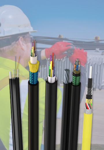 Fiber Optic Cable
 Fiber Optic Tools
 Ethernet Cable
 Coaxial Cable
 Fire & Security Cable
 Voice, Audio & Video
 Power & Control Cable