In many data center projects, the cabling bill of materials is treated as a downstream technical output: count the racks, calculate fiber cores, select cable types, add ODFs and patch cords, then issue the BOM for procurement. That workflow is convenient, but it misses one of the most important project realities: a data center is not built around cable first. It is built around available power.
Before a fiber cabling BOM is frozen, the project team should confirm whether the required electrical capacity is actually available, when it can be energized, and how the capacity will be phased. Without that confirmation, the BOM may over-order materials for halls that cannot go live, under-plan routes for the first powered phase, or miss the redundant entrance and cross-connect requirements that operators will need when traffic is activated.
Why Data Center Projects Are Constrained by Power Access
Modern data centers are power-intensive infrastructure assets. AI workloads, high-density racks, and accelerated cloud growth have made electricity access one of the first project constraints. The International Energy Agency discusses the rising electricity demand connected with AI and digital infrastructure growth, as well as grid infrastructure constraints that affect large electrical loads.

For cabling planners, this means a site may have approved land, a building shell, and a conceptual network design before it has confirmed utility capacity. There is a major difference between a planned 40 MW campus and a first phase that can only energize 8 MW. If the cabling BOM is created for the final 40 MW layout without understanding the 8 MW start-up phase, procurement may become misaligned with the real deployment sequence.
Power availability affects cabling in several direct ways:
- Which data halls will be live first.
- How many racks will be installed, powered, and connected in the first phase.
- Which Meet-Me Rooms, telecom rooms, and MMR-to-data-hall routes must be prioritized.
- Whether redundant fiber entrances are required from day one or reserved for a later phase.
- How much ODF, patching, labeling, tray capacity, and installation labor should be procured immediately.
Power Site, Data Center Site, and Fiber Route: A Connected Planning Triangle
A data center project is rarely defined by the building footprint alone. Three locations or route systems must be considered together: the power site, the data center site, and the fiber route. If one of them changes, the cabling BOM often changes as well.

| Planning element | What it determines | Why it matters to the cabling BOM |
|---|---|---|
| Power site | Utility substation, transformer yard, power corridor, switchgear location, or temporary power arrangement. | Defines when the site can be energized and which halls or buildings can be activated first. |
| Data center site | Building layout, MMR position, data halls, white space, equipment rooms, and rack blocks. | Defines the internal cabling topology, ODF locations, rack count, pathways, and patching architecture. |
| Fiber route | Carrier routes, ducts, handholes, campus backbone paths, and outside plant entry points. | Determines external cable lengths, diversity design, entry rooms, splice points, and delivery sequence. |
These three elements should be checked together before the BOM is finalized. A revised power corridor may affect the civil works plan and pathway access. A delayed utility connection may shift which building or hall becomes phase one. A change in first-phase halls may change the required backbone cable lengths, ODF port quantities, patch cord volumes, and labeling plan.
Primary and Redundant Fiber Entrance
Fiber entrance design is one of the easiest areas to under-scope when power status is unclear. Many projects have a primary fiber entrance defined in the early site plan, while the redundant entrance is treated as a later detail. That can be risky for a carrier-neutral or high-availability data center.

Uptime Institute's Tier concepts emphasize infrastructure topology, maintainability, and fault tolerance in data center design. While cabling diversity is only one part of the wider infrastructure model, the same operational thinking applies: if a facility is expected to support resilient services, route diversity should be designed deliberately rather than improvised after the first phase goes live.
Before issuing the cabling BOM, confirm the following:
- Where the primary fiber entrance enters the site.
- Where the redundant entrance enters and whether it is physically diverse.
- Whether both routes are required for the first powered phase.
- Which carriers or network providers will use each entrance.
- Whether ducts, manholes, handholes, splice closures, and entrance rooms are ready for installation.
Campus Backbone and Internal Data Hall Cabling
Once power phasing is confirmed, the cabling team can separate two scopes that are often mixed together: campus backbone cabling and internal data hall cabling.
Campus Backbone
The campus backbone connects entrance facilities, Meet-Me Rooms, network rooms, buildings, and sometimes multiple data halls across a larger site. This scope may include high-count outdoor fiber cable, pre-terminated trunk cable, innerduct, splice closures, patch panels, and pathway accessories.
Backbone planning should answer these questions:
- Which building or hall is energized first?
- Which backbone paths must be installed before the first tenant or IT load arrives?
- Which paths should be reserved for later phases but not fully populated yet?
- Is the pathway capacity designed for ultimate buildout even if cable procurement is staged?
Internal Data Hall Cabling
Internal cabling includes connections from MMRs, network rooms, and ODFs to server rows, cabinets, or active equipment zones. This scope is more sensitive to rack density and deployment timing. If the first powered phase includes only part of a hall, the BOM should reflect the actual rack blocks that will be commissioned first while protecting an expansion path for the next blocks.
Structured cabling decisions such as topology, pathways, media selection, and administration should be planned as part of an integrated system rather than isolated material counts. This is especially important when the first powered hall, future expansion path, and carrier entrance plan are not identical.
ODF, Rack, and Patching Scope
ODFs, racks, and patching are often where power uncertainty turns into cost uncertainty. A BOM may include enough ODF frames, adapter panels, cassettes, patch cords, and management accessories for the final hall count. However, if only a limited number of racks can be energized in the first stage, buying and installing everything at once may tie up budget and create unnecessary handling risk.
| BOM item | Power-related question | Recommended planning approach |
|---|---|---|
| ODF frames | How many halls and MMRs will be live in phase one? | Install base frame capacity for the first live phase; reserve floor space and expansion positions for future frames. |
| Adapter panels and modules | How many ports are required for energized racks? | Procure active-phase port capacity plus a controlled spare percentage. |
| Rack patching | Which cabinets will be powered and commissioned? | Align patch cords, cable managers, and labels with the commissioning sequence. |
| Cable trays and pathways | Will future phases use the same route? | Build pathway capacity for ultimate growth where access will become difficult later. |
| Spare ports and jumpers | How quickly will the next load block be energized? | Hold spares for operational flexibility, but avoid excessive early stock for delayed power phases. |
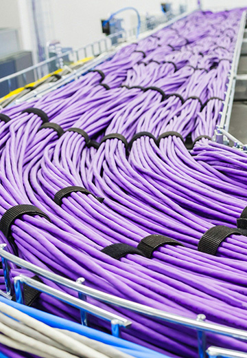
Patch cord management also matters operationally. Dense patching areas can become difficult to maintain if cable length, bend radius, labeling, slack storage, and pathway separation are not planned from the start.
Cable Labeling Should Follow Power and Commissioning Phases
Labeling is not just an installation detail. It is a project control tool. A good labeling system helps teams identify which cables belong to phase one, which are reserved for phase two, which routes are primary, which are redundant, and which connections are active, tested, spare, or future-use.
For data center cabling BOMs, labeling materials should be planned with the same discipline as fiber cable and patch panels. Include durable cable labels, panel labels, rack labels, pathway labels, and documentation updates in the BOM. More importantly, confirm that the naming convention matches the phased power and commissioning plan.
A practical label format may include:
- Building or hall identifier.
- Phase number or load block.
- Route type: primary, redundant, carrier, campus backbone, or internal.
- ODF, rack, panel, and port identifier.
- Test status or commissioning status.
When the power schedule changes, the labeling schedule may also need to change. If the BOM ignores this, the project may receive the right cable but the wrong administration materials.
Staged Delivery: Matching Material Flow to Energization
A staged delivery strategy allows the cabling BOM to support both immediate deployment and long-term expansion. The goal is not to reduce the design standard. The goal is to procure and deliver materials in the order that the project can actually use them.

| Delivery stage | Typical cabling scope | Reason for staging |
|---|---|---|
| Stage 1: Site readiness | Entrance ducts, backbone pathway, route markers, initial ODF frames, essential labeling. | Supports civil readiness and carrier connection before full IT load deployment. |
| Stage 2: First energized phase | Primary and required redundant routes, active hall backbone, first rack block patching, test documentation. | Matches the first confirmed power capacity and commissioning schedule. |
| Stage 3: Expansion blocks | Additional ODF modules, trunk cables, patch cords, labels, cable managers, and rack accessories. | Supports future halls or rack rows as additional power becomes available. |
| Stage 4: Operational spares | Spare patch cords, replacement modules, extra labels, and maintenance stock. | Maintains operational flexibility without overloading early-stage inventory. |
Staged delivery is especially important when lead times vary by product. High-count fiber cables, custom pre-terminated trunks, ODF frames, and specialty accessories may need early commitment, while some patching and labeling items can be released closer to commissioning.
Project Readiness Checklist Before Finalizing the Cabling BOM
Before releasing a data center cabling BOM for procurement, the project team should confirm the following readiness items.
Power and Phasing
- Utility capacity is confirmed, not only requested or assumed.
- First energization date is documented.
- Phase-one load capacity is clear.
- Future energization phases are mapped to halls, buildings, or rack blocks.
- Temporary power assumptions, if any, are separated from permanent capacity assumptions.
Site and Route
- Power site, data center site, and fiber route are reviewed together.
- Primary and redundant fiber entrance points are confirmed.
- Outside plant pathways, ducts, manholes, handholes, and entry rooms are available or scheduled.
- Carrier route responsibilities and demarcation points are documented.
- Any route conflict with power corridors, civil works, or security zones has been resolved.
Campus Backbone
- Backbone capacity supports both phase-one deployment and future expansion.
- Cable lengths are based on verified routes, not conceptual drawings only.
- Diverse paths are separated where resilience requires it.
- Splice points, pull points, and slack storage areas are included.
- Pathway capacity is reserved for later phases where access will become constrained.
ODF, Rack, and Patching
- ODF frame and module quantities match the first powered phase.
- Rack count is based on commissioned racks, not only planned future racks.
- Patch cords are specified by connector type, length, polarity, fiber type, and phase.
- Cable management accessories are included for dense patching zones.
- Spare capacity is controlled and justified.
Labeling and Documentation
- Labeling convention matches the site, hall, phase, route, rack, panel, and port structure.
- Primary and redundant routes are clearly identified.
- Labels are included for cables, panels, racks, trays, and documentation records.
- Test documentation and as-built requirements are included in the delivery scope.
- Change control is in place for power or route schedule changes.
Procurement and Delivery
- Long-lead cabling items are identified early.
- Delivery stages match energization and commissioning milestones.
- Storage, handling, and site access plans are confirmed.
- Vendor responsibilities for pre-termination, testing, packaging, and labeling are clear.
- Contingency quantities are agreed before purchase orders are issued.
Planning References
The following external resources provide additional context for data center power demand, resilience planning, structured cabling, and fiber patch management:
- IEA: Energy Demand from AI
- IEA: Electricity 2026 - Grids
- Uptime Institute: Tier Classification System
- Corning: Structured Cabling Design White Paper
- CommScope: Patch Cord Management for Fiber Optic Solutions
- CommScope: Accelerated Cabling Deployments
Conclusion
A data center cabling BOM is not just a material list. It is a reflection of the project's electrical reality, construction sequence, network resilience target, and operational readiness. If power availability is uncertain, the BOM is also uncertain.
By confirming power capacity, energization dates, route readiness, fiber entrance diversity, ODF scope, patching requirements, labeling standards, and staged delivery needs before procurement, project teams can reduce rework, avoid stranded inventory, and support a smoother path from construction to live service.
The best cabling BOM is not necessarily the largest or earliest one. It is the one that matches the confirmed power plan and still protects the data center's long-term growth.
FAQ
Why should power availability be confirmed before a data center cabling BOM?
Power availability determines which halls, racks, entrances, ODFs, routes, labels, and delivery stages can be commissioned first. If the BOM is based only on the final master plan, it may over-order delayed areas or miss the first live phase.
Does a delayed power connection change the fiber cabling scope?
Yes. A delayed or phased power connection can change the first live hall, backbone route priority, rack patching quantity, redundant entrance timing, labeling plan, and procurement sequence.
Which information should be checked before releasing the BOM?
Confirm utility capacity, energization dates, phase-one load capacity, data hall sequence, primary and redundant fiber entrances, verified cable routes, ODF port scope, rack count, labeling rules, testing requirements, and staged delivery needs.
Can pathway capacity be planned for full buildout while materials are staged?
Yes. Many projects reserve tray, duct, room, and floor-space capacity for future buildout while procuring active fiber, ODF modules, patch cords, and labels according to confirmed energization phases.



 Fiber Optic Cable
 Fiber Optic Tools
 Ethernet Cable
 Coaxial Cable
 Fire & Security Cable
 Voice, Audio & Video
 Power & Control Cable