Quick Answer: Flexible Cable vs Continuous-Flex Cable
A flexible cable is easier to bend during routing, installation, maintenance, or limited repositioning. A continuous-flex cable is designed and tested for repeated bending over many cycles in a controlled path, commonly inside a cable carrier. A torsion cable is intended for repeated twisting. These labels describe different mechanical duties, so one should not be substituted for another without data for the exact motion.
The practical buying rule is simple: do not specify only “flexible.” State how the cable moves and request model-specific limits for that duty. The electrical design still matters, including voltage, current, conductor count, shielding, and jacket requirements, but movement becomes an additional selection axis.
Compare the Three Cable Movement Categories
The most useful first step is to place the application into one of three movement categories. A machine may contain all three, so different cable sections can require different constructions.
| Duty | Typical movement | Evidence to request | Typical selection risk |
|---|---|---|---|
| Fixed or occasional flexing | Installation bends, maintenance access, vibration, or limited repositioning. | Minimum installation bend radius, support method, and environmental limits. | Assuming a soft cable is suitable for continuous movement. |
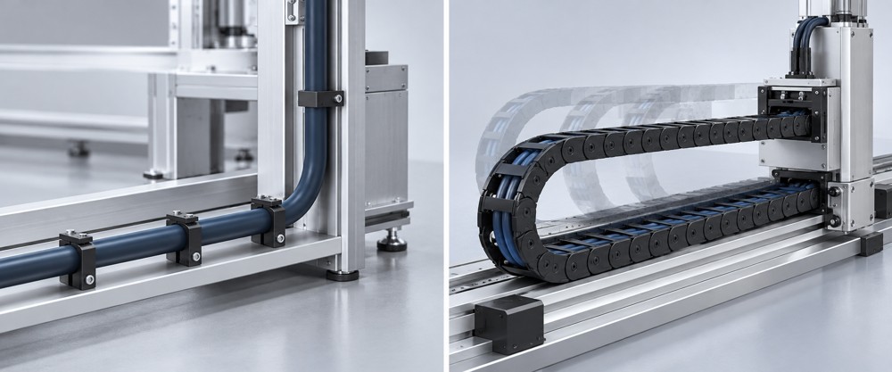
| Continuous flexing | Repeated linear travel and bending, often in a cable carrier. | Dynamic radius, travel, speed, acceleration, cycles, load, and test temperature. | Comparing cycle counts without comparing test conditions. |
| Torsion | Repeated angular twisting around the cable axis. | Twist angle, reference length, speed, cycles, and temperature. | Treating drag-chain data as proof of torsion performance. |
Why Cable Construction and Test Conditions Change
Continuous motion places repeated mechanical stress on conductors, insulation, fillers, shields, and jackets. A continuous-flex design may use finer conductor strands, an optimized conductor lay, suitable fillers or separators, and jacket materials selected for the motion and environment. The complete finished cable must work as a system.
Fine strands alone do not establish continuous-flex performance. Likewise, a cable that bends easily by hand is not automatically suitable for millions of cycles. Buyers should evaluate the complete construction together with model-specific test evidence and the intended installation method.
Strand size, lay, conductor arrangement, and insulation interact during repeated motion.
Fillers, separators, pair arrangement, and shielding influence stability and stress distribution.
Oil, coolant, abrasion, temperature, and carrier contact can change the required material.
Define the Motion Profile Before Selecting Cable
A purchasing description should convert “the cable moves” into measurable conditions. Record the real machine motion at the cable location, not only the overall machine type.
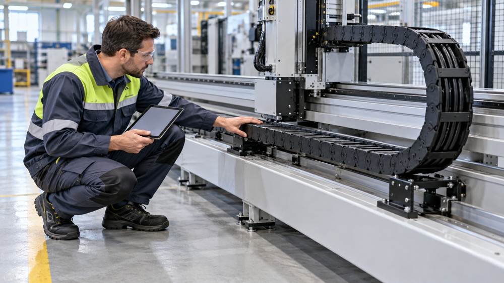
- Identify the movement. Is it bending, rolling, twisting, or a combination?
- Measure the geometry. Record the minimum bend radius, travel length, cable-carrier dimensions, and fixed or moving ends.
- Define the dynamics. State speed, acceleration, duty cycle, operating hours, and the required service-life target.
- Map the environment. Include temperature, oil, coolant, abrasion, dust, moisture, and cleaning exposure.
- Confirm the electrical function. State voltage, current, conductor count and size, signal type, shielding, and termination method.
How to Compare Continuous-Flex Ratings
A cycle-life claim is meaningful only when its test conditions resemble the application. Two cables with the same headline cycle count may have been tested at different radii, travel lengths, speeds, temperatures, orientations, or cable loads.
| Test detail | Why it matters | What to compare |
|---|---|---|
| Dynamic bend radius | A smaller radius generally increases mechanical stress. | Test radius versus the installed carrier radius. |
| Travel and speed | Longer or faster motion changes stress and heat generation. | Machine travel, velocity, and test stroke. |
| Acceleration | Rapid direction changes add dynamic load. | Peak machine acceleration and test profile. |
| Cable load and carrier | Fill, separation, support, and carrier geometry affect motion. | Installation arrangement and test setup. |
| Temperature and fluids | Materials respond differently under heat, cold, oil, or coolant. | Operating environment and test limits. |
| Failure criteria | Electrical continuity and visible jacket damage may be assessed differently. | The supplier's stated pass/fail method. |
Procurement shortcut: request the test method and conditions beside the cycle figure. A standalone cycle number is not enough to establish equivalence between suppliers.
Match the Cable Type to the Application
Start with the movement duty, then add the electrical and environmental requirements. The result may be a standard flexible control cable for protected fixed routing, a continuous-flex cable for a cable carrier, or a torsion-rated construction for repeated twisting.
| Application | Likely motion class | Key checks before ordering |
|---|---|---|
| Control cabinet or protected machine wiring | Fixed or occasional flexing | Installation radius, conductor schedule, shielding, terminals, oil, and temperature. |
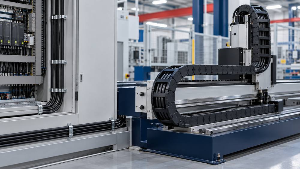
| Linear axis, shuttle, or gantry carrier | Continuous flexing | Carrier radius, travel, speed, acceleration, cycles, fill, and jacket exposure. |
| Robot wrist or rotating tool | Torsion or combined motion | Twist angle per length, speed, cycles, routing, and strain relief. |
| Sensor or actuator branch | Depends on device and route | Connector interface, pin assignment, signal type, flex duty, jacket, and replacement access. |
For initial sourcing, review ZION's flex control cable category and flex control and data cable range. For connectorized device branches, compare the interface and movement requirements with the available sensor and actuator cables.
Common Specification Mistakes
- Using “flexible” as the complete motion requirement. This does not state whether the cable is installed once, moved occasionally, or bent continuously.
- Listing a cycle target without test conditions. Radius, travel, speed, acceleration, temperature, and carrier arrangement are needed for comparison.
- Installing below the verified bend radius. Tighter bending generally increases stress and can shorten service life.
- Using continuous-flex data as torsion proof. Linear repetitive bending and angular twisting require different evidence.
- Selecting only by purchase price. Downtime, replacement access, machine speed, and failure consequence also affect the economical choice.
- Ignoring the complete cable. Conductors, insulation, shield, core design, and jacket must perform together.
Information Needed for Cable Selection and Quotation
Send a complete technical schedule so suppliers can compare the correct constructions and return model-specific documentation. Unknown values can be marked for review rather than replaced with assumptions.
- Machine or equipment application
- Circuit function and connected devices
- Bending, rolling, torsion, or combined motion
- Minimum bend radius and travel length
- Speed, acceleration, cycles, and service target
- Cable carrier size, fill, and installation arrangement
- Rated voltage, current, cores or pairs, and conductor size
- Shielding and termination requirements
- Oil, coolant, abrasion, temperature, and cleaning exposure
- Applicable standards, approvals, quantity, and destination
ZION's broader control cable category can support the initial family review. Final selection should use the exact model datasheet and motion evidence that match the installation.
Frequently Asked Questions
Can a standard flexible cable be used in a drag chain?
Only when the exact cable is rated and tested for the required repetitive bending duty under suitable radius, travel, speed, acceleration, cycle, load, and environmental conditions. General flexibility alone is not evidence of drag-chain suitability.
Does a smaller bend radius mean longer cable life?
No. A smaller bend radius generally increases mechanical stress. Use the dynamic bend-radius limit and installation method stated for the exact cable.
Is a continuous-flex cable also suitable for torsion?
Not automatically. Repetitive linear bending and repeated angular twisting are different duties. Torsion suitability requires model-specific data for twist angle, reference length, speed, cycles, and temperature.
What information should be included in a continuous-flex cable enquiry?
Provide the application, circuit function, motion type, bend radius, travel, speed, acceleration, cycle target, carrier details, voltage, current, conductor count and size, shielding, jacket exposure, temperature, standards, quantity, and destination.



 Fiber Optic Cable
 Fiber Optic Tools
 Ethernet Cable
 Coaxial Cable
 Fire & Security Cable
 Voice, Audio & Video
 Power & Control Cable