Quick Answer: How Should Control Cables Be Routed Near Power Cables?
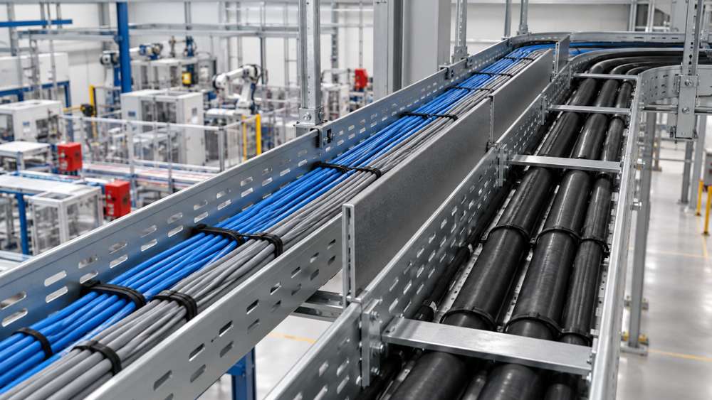
Route sensitive control cables away from power, motor, and drive conductors whenever practical. Use separate trays, compartments, or defined zones where required; minimize long parallel runs; make unavoidable crossings short and close to a right angle; and preserve segregation at cabinet entries. Shielding can reduce coupling, but it does not replace physical separation or the equipment manufacturer's routing requirements.
The correct layout starts with the circuits, not a universal distance. A low-energy steady supply, a switched contactor circuit, and a VFD motor output can create very different interference environments. The control side also varies: relay wiring is generally less sensitive than low-level analog measurement, encoder, feedback, or communication circuits.
Identify the Interference Source and the Sensitive Circuit
Before selecting a tray or deciding how much separation is needed, classify both sides of the route. The source circuit determines the potential disturbance, while the control circuit determines how easily that disturbance may affect machine operation or measurement quality.
| Circuit or equipment | Routing concern | Planning response |
|---|---|---|
| VFD or servo motor output | Fast switching and motor-current paths can create a severe local interference environment. | Prioritize dedicated containment, short crossings, and the drive manufacturer's cable and bonding instructions. |
| Welding, large contactors, switched inductive loads | Transient events and high current can couple into nearby control wiring. | Increase route control around switching equipment and avoid shared bundles with sensitive circuits. |
| Analog, encoder, feedback, or communication | Low-level or timing-sensitive signals may be more susceptible to coupled noise. | Use the equipment-specified cable construction, shielding, termination, and segregation method. |
| Relay and conventional discrete control | Often more tolerant, but still affected by strong sources or poor route design. | Classify the actual load and switching environment rather than treating all control wiring as identical. |
Plan Separate Routes Before Cable Installation
Route planning is most effective before trays, ducts, and gland plates are full. Mark the source equipment, field devices, cabinet entries, required service points, and unavoidable transition zones. Then assign containment so the route remains practical from end to end.

- Assign separate containment or compartments where the equipment or project rules require segregation.
- Avoid combining sensitive control circuits with drive output conductors in the same bundle.
- Keep the required route separation through vertical drops, equipment transitions, and field junctions.
- Plan enough tray capacity and support so later additions do not force the circuits into the same space.
- Record the intended route on drawings so installation and inspection teams assess the same layout.
Control Parallel Runs, Crossings, and Difficult Transition Points
Coupling risk generally increases when power and control cables remain close and parallel for a long distance. Where routes must meet, a short crossing close to 90° is usually preferable to an extended shared direction. This reduces common exposure but does not cancel every conducted or radiated disturbance.
| Location | Hidden routing risk | Design or inspection action |
|---|---|---|
| Long tray run | Extended parallel coupling beside motor or drive conductors. | Use separate containment or the project-approved compartment arrangement. |
| Tray crossing | The routes turn and run together after the nominal crossing point. | Keep the crossing short and close to 90° where practical. |
| Vertical drop or riser | Segregation is lost where horizontal trays converge. | Continue defined zones through the complete transition. |
| Service loop | Unnecessary slack creates a new parallel section beside power wiring. | Keep only required slack and support it in the assigned control-cable zone. |
| Maintenance bypass | Temporary routing becomes permanent and crosses high-energy conductors. | Provide a documented, supported route for repair and future replacement. |
Choose Separation Distance From Documented Project Requirements
A single distance such as 100 mm, 200 mm, or 300 mm is not valid for every installation. Required separation can change with voltage, current, switching waveform, cable construction, shielding, route length, tray material, bonding, and the applicable equipment or project standard.
Rated voltage and current do not describe every disturbance; switching behavior and the connected load also matter.
A short crossing and a long parallel run create different coupling conditions even when the closest distance is identical.
Metallic trays, dividers, conduit, and their bonding details can change how the route behaves.
Procurement action: when a separation distance is included in a cable schedule or installation drawing, record its source and conditions so panel builders, installers, and inspectors apply the same requirement.
Coordinate Shielding, Bonding, and Metallic Containment
Shielding is one part of the EMC design. A screened cable may reduce electric-field coupling, but its performance depends on the screen construction, termination method, panel entry, and bonding path. It does not authorize unsafe mixing of circuits or override required segregation.
When a metallic tray, divider, conduit, enclosure, or gland plate is intended to support EMC control, verify the complete bonding path rather than checking only one section. Tray joints, cabinet transitions, painted surfaces, and removable panels can interrupt the intended path. The cable shield should be terminated according to the connected equipment and project grounding plan.
For candidate products, ZION lists screened and unscreened options in its Flex Control Cable category and Flex Control Cable / Data Cable product list. Confirm the exact screen, conductor, jacket, movement, and approval data for the selected model and size.
Preserve Separation at Cabinet Entries and Terminal Areas
A well-separated field route can fail at the final meter if control and power cables converge on one gland plate, share a dense service loop, or cross repeatedly inside the panel. Entry zones should support the same circuit classification used for the external route.
- Assign distinct gland or entry zones for sensitive control and higher-energy conductors.
- Keep internal routing separated until each circuit reaches its designated termination area.
- Support cable weight and service slack so maintenance does not pull routes together.
- Coordinate shield termination hardware with the entry plate and the intended bonding structure.
- Leave enough physical access for inspection, replacement, and future circuit identification.
Field Inspection Checklist and Corrective Priorities
Inspection should follow the actual route from the field device to the panel. Photographs and marked drawings make hidden convergence points easier to review, especially after later machine modifications.
- Trace the complete route. Identify power sources, drive outputs, sensitive circuits, shared containment, and cabinet entries.
- Measure parallel exposure. Record where control and power cables remain close and travel in the same direction.
- Check crossings. Verify that unavoidable crossings are short and do not turn into a shared route.
- Inspect support and slack. Look for loose bundles, unsupported drops, oversized service loops, and later cable additions.
- Verify shielding and bonding. Check the intended shield termination and continuity of relevant metallic containment.
- Correct the highest-exposure sections first. Prioritize long parallel runs beside drive or motor conductors and sensitive signal circuits.
- Update the project record. Mark the final route, entry method, shield treatment, and any approved deviations.
Select Cable Construction for the Circuit and Route
Routing and cable selection should be decided together. Shielding addresses EMC coupling; mechanical protection addresses abrasion, impact, and installation stress; continuous-flex construction addresses defined repeated motion. One feature does not automatically provide the others.
| Selection question | What to confirm before ordering |
|---|---|
| Is shielding required? | Signal sensitivity, nearby source circuits, screen construction, termination method, and equipment instructions. |
| Is mechanical protection required? | Abrasion, impact, crush, oil, chemical, outdoor, and tray or conduit exposure. |
| Will the cable move? | Fixed, occasional flex, continuous flex, torsion, travel, bend radius, speed, and expected cycle duty. |
| Are twisted pairs needed? | Interface design, pair count, circuit assignment, and any impedance or electrical requirements from the equipment documentation. |
| Are standards or approvals required? | The exact standard, market, equipment scope, and model- and size-specific supporting documents. |
For machine-side sensor and actuator connections, review the confirmed interface and environmental requirements before using the Sensor & Actuator Cables range as a shortlist. For broader cable-family selection, the Control Cable product category provides the appropriate starting point.
Information Needed for Cable Selection and Route Review
A complete technical schedule helps the cable supplier and project team separate cable-construction questions from installation-layout questions. Include unknown items explicitly so they can be resolved before the BOM is finalized.
- Application, circuit function, machine, and connected device models
- Rated voltage, operating current, signal or interface type
- Total cable length and the length routed beside power conductors
- Nearby power, motor, VFD, servo, welding, or switching circuits
- Core or pair count, conductor size, and any twisting requirement
- Shield construction, termination method, and bonding plan
- Tray, conduit, compartment, cabinet-entry, and service-loop details
- Fixed or moving duty, bend radius, travel, speed, and cycle expectation
- Temperature, oil, chemicals, UV, moisture, abrasion, and mechanical exposure
- Applicable standards, approvals, test documents, quantity, and destination
Attach a route drawing, cabinet-entry detail, or existing cable datasheet when available. This gives the supplier enough context to evaluate the candidate cable while the project engineer confirms the final routing and segregation method.
Frequently Asked Questions
Can a shielded control cable share a tray with a power cable?
Do not assume that shielding permits shared containment. Check the applicable segregation rules, equipment instructions, tray arrangement, circuit characteristics, and project EMC requirements.
Does crossing power cable at 90 degrees eliminate interference?
A short crossing near 90 degrees can reduce coupling compared with a long parallel route, but it does not eliminate every conducted or radiated disturbance.
What separation distance should be used between control and power cables?
Use the distance specified by the applicable equipment instructions and project electrical or EMC requirements. The correct value depends on circuit energy, switching waveform, route length, cable construction, shielding, and containment.
What information is needed to select a control cable for a mixed-power route?
Provide the circuit function, equipment, voltage, current, route length, nearby power or drive circuits, conductor size, core or pair count, shielding and jacket requirements, movement, environment, standards, quantity, and destination.



 Fiber Optic Cable
 Fiber Optic Tools
 Ethernet Cable
 Coaxial Cable
 Fire & Security Cable
 Voice, Audio & Video
 Power & Control Cable