What Is the Best Cable for an Industrial Sensor?
There is no single cable that is best for every industrial sensor. The correct choice matches the sensor signal and pinout, conductor or pair arrangement, voltage and current requirements, electromagnetic environment, cable route, jacket exposure and movement duty.
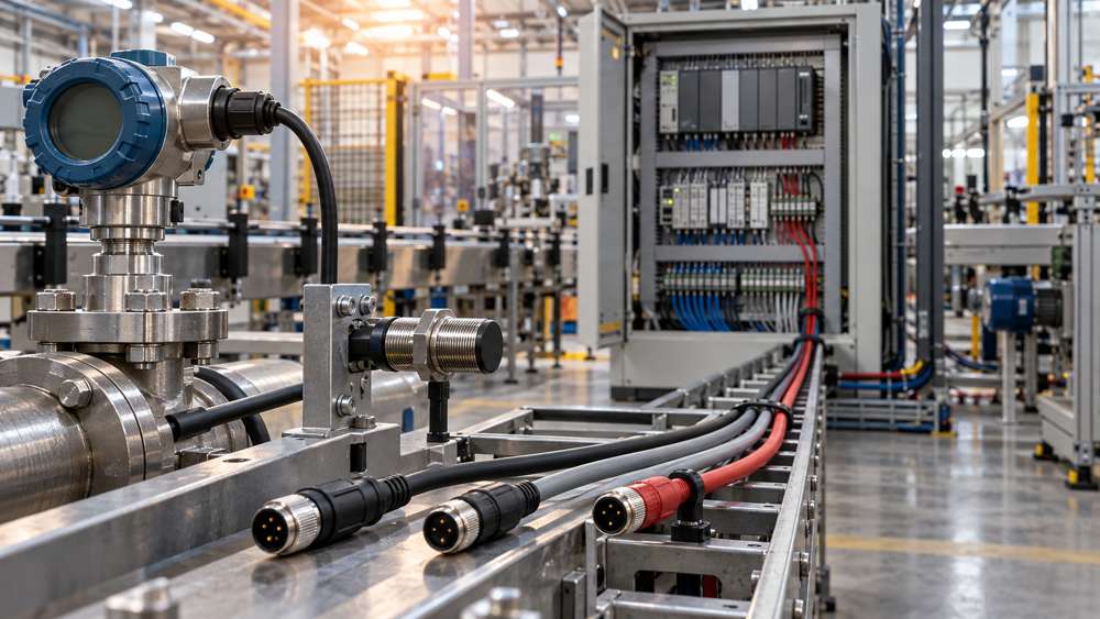
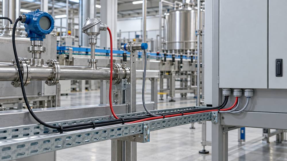
For many analogue measurement circuits, a suitably sized twisted pair is a practical starting point. A shielded construction may be appropriate near variable-frequency drives, motors or power cables, or when required by the sensor or controller manufacturer. Discrete sensors may use multicore or sensor/actuator cable, while RS485 and other digital interfaces require protocol-specific electrical verification.
Match the Cable to the Sensor Signal Type
The signal type determines which electrical characteristics deserve priority. Confirm the device manual and terminal arrangement before deciding on cores, pairs or screening.
| Signal type | Typical use | Key cable checks |
|---|---|---|
| Discrete switching | Proximity, limit and photoelectric sensors | Supply voltage, load current, core count, pinout and distance |
| 4–20 mA | Pressure, flow, level and temperature transmitters | Loop resistance, voltage budget, pair integrity and EMI exposure |
| 0–10 V | Position, pressure and control feedback | Conductor resistance, reference stability, route length and noise |
| RTD | PT100 and PT1000 temperature measurement | 2-, 3- or 4-wire arrangement, lead resistance and conductor balance |
| Digital communication | RS485-based sensors, IO-Link and other interfaces | Protocol impedance, capacitance, topology, termination and device instructions |
4–20 mA current loops
Current loops can provide robust industrial measurements, but cable resistance still consumes part of the available voltage. For a preliminary check, calculate cable voltage drop = loop current × total conductor loop resistance. Include the transmitter requirement, receiver burden and any specified overrange or fault current in the voltage budget.
0–10 V and RTD circuits
Voltage signals can be affected by conductor resistance, reference potential differences and induced noise. RTD measurements are directly influenced by lead resistance, so the 2-, 3- or 4-wire arrangement must follow the instrument diagram; a three-wire RTD also depends on suitable conductor resistance balance.
Digital sensor interfaces
Do not treat every twisted-pair control cable as a communication cable. RS485 and other interfaces can impose characteristic impedance, capacitance, topology and termination requirements that must be verified against the connected equipment.
Multicore vs. Twisted-Pair Sensor Cable
Multicore cables place several insulated conductors under one jacket and are commonly used for switching signals, auxiliary control and general equipment interconnections. Twisted-pair cables organize two conductors as a pair so both experience a more similar electromagnetic environment, which can help reduce induced differential interference.
| Feature | Multicore cable | Twisted-pair cable |
|---|---|---|
| Arrangement | Individual insulated cores | Conductors organized into pairs |
| Common uses | Switching, auxiliary control and general interconnection | Analogue measurement and selected differential data circuits |
| Noise behavior | Depends on construction and installation | Pair balance can reduce certain induced interference |
| Selection basis | Core count, electrical load and environment | Signal type, pair count, electrical data and environment |
Twisting does not guarantee noise-free operation. Routing, grounding, shield termination and receiver characteristics remain part of the complete design.
When Does a Sensor Cable Need Shielding?
Evaluate a shielded sensor cable when low-level analogue wiring runs near drives, motors, contactors, welding equipment, switching power supplies or power cables, or when the equipment manufacturer specifies screened wiring.
The signal is tolerant, the route is separated from significant EMI, the installation is electrically quiet and the equipment instructions permit it.
The circuit is noise-sensitive, the route passes near interference sources, a known noise issue exists or screened wiring is specified.
An overall shield surrounds the conductor group or pair bundle. Individually screened pairs add separation between selected circuits, but their presence must be confirmed from the exact cable construction. The letters “TP” alone do not establish individual pair screening.
Shield termination is a system decision. Single-ended or both-end bonding may be appropriate under different frequency, potential difference and enclosure-bonding conditions. Follow the approved EMC plan and equipment instructions, and never use a cable shield as a protective earth conductor.
Check the Distance and Complete Cable Route
There is no universal maximum distance for every industrial sensor cable. Practical length depends on conductor resistance, capacitance, signal source and receiver, protocol, supply voltage and the electromagnetic environment.
- Measure the installed path, including cabinet routing, vertical drops, junction boxes and service loops.
- Identify motor feeders, inverter outputs, contactors, welding equipment and high-current conductors along the route.
- Apply the separation and crossing practices required by the equipment and installation standard.
- Include motion, strain relief, cable entry and bend radius at both the machine and cabinet ends.
A cable that satisfies an electrical calculation can still deliver unreliable measurements when routing, grounding or termination is poorly controlled.
PVC vs. PUR Sensor Cable
PVC is often a practical option for protected, fixed industrial routes within its documented ratings. PUR is commonly evaluated where abrasion, oil exposure and machine-side handling are more demanding. The material name alone is not a complete performance specification.
| Installation condition | Selection direction |
|---|---|
| Protected fixed indoor route | Consider a PVC sensor cable with suitable documented ratings |
| Machine-side abrasion | Evaluate PUR and the complete mechanical construction |
| Oil or coolant exposure | Verify resistance to the actual substance and concentration |
| Occasional movement | Confirm permitted flexing and bend radius |
| Continuous drag-chain motion | Require documented continuous-flex performance for the motion profile |
| Outdoor or wet route | Verify UV, moisture and installation approvals |
A flexible cable is not automatically a continuous-flex cable. For repeated motion, specify dynamic bend radius, travel distance, acceleration, torsion and the required flex-life evidence.
Which ZION Cable Family Fits the Application?
ZION cable families provide starting points for industrial sensor and control wiring. Final selection requires the current product data and the connected equipment requirements.
| Cable family | Typical selection direction | Verify before ordering |
|---|---|---|
| LiYY TP | Unshielded twisted-pair signal and selected control wiring | Pair count, conductor size, voltage and environment |
| LiYCY TP | Shielded twisted-pair analogue and selected control signals | Screen construction, termination and electrical data |
| LiYY | General multicore signal and control interconnection | Core count, current, voltage and environment |
| LiYCY | Shielded multicore control wiring | EMI need, grounding and exact construction |
| PVC sensor & actuator | Protected fixed machine-side sensor wiring | Pinout, dimensions and mechanical conditions |
| PUR sensor & actuator | Machine-side wiring with higher abrasion or environmental demands | Oil exposure, movement, shield option and flex rating |
Explore confirmed ZION ranges for LiYY and LiYCY flex control cable, PVC and PUR sensor and actuator cables, and the wider industrial automation control cable solution.
Selection Example: 4–20 mA Pressure Transmitter to PLC
Consider a 4–20 mA pressure transmitter installed on a production line near motor-driven equipment and connected to a PLC analogue input module.
- Confirm the circuitIdentify whether the transmitter is two-wire loop-powered or uses a different power and output arrangement.
- Calculate the voltage budgetCheck the supply voltage, transmitter requirement, input burden and estimated loop conductor resistance.
- Review the routeMeasure the installed length and identify proximity to drives, motors and power conductors.
- Select the conductor arrangementEvaluate a suitably sized twisted pair against the transmitter and PLC instructions.
- Decide on shieldingUse the noise exposure, manufacturer requirements and grounding plan to evaluate a shielded twisted-pair option.
- Match the environmentCheck oil, abrasion, moisture, temperature and movement at the sensor end and along the full route.
- Document installation detailsRecord shield termination, cable entry, strain relief, routing and conductor identification.
Industrial Sensor Signal Cable Buying Checklist
A complete enquiry allows the supplier and engineering team to compare suitable constructions without relying on a cable family name alone.
| RFQ field | Information to provide |
|---|---|
| Application | Pressure, temperature, proximity, level, flow or other sensor duty |
| Equipment | Sensor and PLC, controller or input-module manufacturer and model |
| Signal | 4–20 mA, 0–10 V, RTD, discrete output or named digital protocol |
| Conductors | Required cores, pairs or triads and conductor size in mm² or AWG |
| Length and quantity | Installed route length, number of runs, order quantity and packing length |
| Shielding | Unshielded, overall shield or individually screened circuits, plus termination plan |
| Installation | Cabinet, tray, conduit, machine, outdoor or exposed route |
| Movement | Fixed, occasional flex, torsion or continuous drag-chain motion |
| Environment | Temperature, oil, coolant, chemicals, moisture, UV and abrasion |
| Compliance | Applicable standards, approvals, test reports, marking and delivery documents |
For replacement work, include a clear photograph of the existing cable marking and the equipment wiring diagram. For a new installation, include the cable schedule or technical specification when available.
Common Sensor Cable Selection Mistakes
Compare pair layout, conductor size, insulation, shielding, electrical ratings and mechanical construction.
Shielding does not replace correct routing, bonding, separation, circuit design or termination.
Protocol compatibility depends on impedance, capacitance, topology and equipment requirements.
Where one cable carries signal and power, verify current capacity, voltage drop and protection.
Dynamic machinery requires documented performance for the real bend, travel and torsion profile.
Verify the jacket against the actual oil, coolant, cleaner, moisture, UV and temperature conditions.
Frequently Asked Questions
What cable is best for a 4–20 mA sensor?
A suitably sized twisted-pair cable is a common candidate. Shielding may be appropriate in electrically noisy routes or where the equipment manufacturer requires it. Confirm the loop voltage budget, cable length and installation conditions.
Can I use an unshielded cable for industrial sensors?
Yes, when the signal, electrical environment, route separation and equipment instructions permit it. Shielding is not mandatory for every sensor circuit.
What is the difference between LiYY TP and LiYCY TP cable?
LiYY TP is an unshielded twisted-pair cable family, while LiYCY TP includes screening. Confirm the exact pair count, conductor size, screen construction and electrical ratings in the current product data.
Is PUR always better than PVC for sensor cables?
No. PVC may suit protected fixed routes, while PUR is often evaluated for abrasion, oil exposure and machine-side handling. Suitability depends on the actual compound, movement and environmental ratings.
Can a standard control cable be used for RS485 sensors?
Only when its impedance, capacitance, pair construction and installation characteristics meet the RS485 equipment and network requirements. A generic control cable is not automatically protocol-qualified.
Does a shielded sensor cable need grounding at both ends?
Not in every installation. Shield termination depends on the circuit, frequency range, equipment design, bonding and EMC plan. Follow the approved grounding strategy and equipment instructions.



 Fiber Optic Cable
 Fiber Optic Tools
 Ethernet Cable
 Coaxial Cable
 Fire & Security Cable
 Voice, Audio & Video
 Power & Control Cable