
1. Define the product category and system boundary first
A fiber-optic payout spool for ROV, UUV and AUV communication releases fine-diameter cable as the vehicle moves. It is not automatically equivalent to a conventional load-bearing ROV tether or umbilical that is repeatedly reeled and may also transmit electrical power. It is also different from a long-life submarine telecommunications cable.
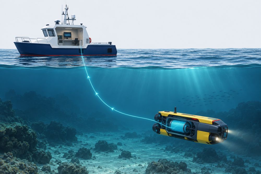
The RFQ must state whether the supplier is quoting a passive spool only or a complete link that includes transceivers, underwater connectors, penetrators, pressure housings, cable assemblies and mounting hardware. This single distinction prevents many interface and scope disputes.
2. Separate listed product data from project-guaranteed values
The current ZION product page lists 1–30 km length options, 0.5 mm and 0.65 mm cable diameters, G.657.A2 single-mode fiber, FC/UPC or LC/UPC interfaces, and 1310 nm or 1550 nm operation. The following values are useful for initial matching, but the final RFQ should request guaranteed values and test records for the ordered length and assembled configuration.
| Item | 0.5 mm version | 0.65 mm version |
|---|---|---|
| Unit weight | 248 g/km | 430 g/km |
| Listed tensile strength | >150 N | >200 N |
| Cable density | 1.25 g/cm³ | 1.3 g/cm³ |
The listed attenuation coefficients are ≤0.35 dB/km at 1310 nm and ≤0.25 dB/km at 1550 nm. At those limits, 30 km of fiber alone contributes approximately 10.5 dB at 1310 nm or 7.5 dB at 1550 nm. Connector, splice, bending, payout-state and engineering margins are additional.
3. Describe the mission and communication architecture
Identify the ROV, UUV, AUV or other vehicle, and state whether the spool is installed on the parent platform, the vehicle or at both ends.
Define control, video, telemetry and sensor traffic, including throughput, end-to-end latency and acceptable packet loss.
State single-use payout, recoverable but not reusable, or reloadable/reusable operation. Do not assume reverse reeling is supported.
Provide route length, duration, speed, turn radius, descent/ascent profile, obstacles and fail-safe behavior after link loss.
Required fiber length should be based on the actual mission path, spool position and contingency reserve rather than straight-line distance alone. The underwater fiber optic spool selection guide can support initial configuration discussions.
4. Specify the payout spool and fine-diameter cable
Static continuity is not enough to characterize a payout system. The RFQ must describe the mechanical conditions that the cable and dispenser will experience during launch and operation.
- Effective deployed length, reserve length, quantity, fiber count, sheath construction, unit weight, density and net submerged weight or buoyancy.
- Minimum breaking load, allowable working load, normal payout tension, peak dynamic load and the applied safety factor.
- Continuous and peak payout speed, acceleration, breakaway force, end-of-pack shock, allowable twist and anti-slack requirements.
- Static and dynamic minimum bend radius, outlet guide or sheave diameter, and minimum winding diameter.
- Payout direction, spool attitude, installation envelope, mass limit, center of gravity, mounting pattern, outlet location and lead length.
- Payout in air, during water entry or fully submerged, including temperature, salinity, sediment, biofouling, oil and other contaminants.
5. Build the optical link and terminal specification
Wavelength selection is only one part of link design. A complete RFQ defines fiber architecture, terminal compatibility, link loss and the operating margin at the specified environmental limits.
- Define fiber type and count. For single-fiber BiDi/WDM, specify the wavelength pair and endpoint orientation. For dual-fiber links, define the Tx/Rx mapping.
- Specify the service interface and rate, such as 100BASE-FX, 1000BASE-X, raw serial data or a supplier-specific protocol. “Network port” alone does not establish compatibility.
- State minimum and maximum transmitter output, receiver sensitivity, receiver overload, target BER and guaranteed performance over the required temperature and input-voltage ranges.
- Specify connector family, polish and interface form, such as FC/UPC plug, LC/UPC duplex plug, bulkhead adapter or equipment receptacle. “Male/female” alone is not a sufficient optical interface definition.
- For active terminals, define voltage range, peak and steady-state consumption, surge and reverse-polarity protection, grounding and power connector. A passive spool itself requires no electrical power.
Available optical budget = minimum Tx power − receiver sensitivity Estimated link loss = fiber loss + connector loss + splice loss + other penalties Engineering margin = available optical budget − estimated link loss 6. Define depth, pressure boundaries and underwater connections
Maximum depth does not fully define a pressure qualification. State the corresponding working pressure, test pressure, hold time, pressure-cycle count, ramp and decompression rates, and acceptance criteria.
- Identify which components retain differential pressure. A free-flooded spool or cable requires different verification from a sealed pressure housing.
- For cable hydrostatic testing, define sample length, pressure, duration, ramp rates, and attenuation limits before, during and after the test. IEC 60794-1-210:2026 may be used as a test method reference, while severity and pass/fail limits remain project-specific.
- For underwater connectors, define dry-mate or wet-mate operation, rated depth, mating cycles, mating under pressure or while energized, materials, locking and keying.
- Define seawater compatibility, galvanic-corrosion control, seal materials, immersion duration, and post-cycle visual, insulation and optical checks.
7. Request drawings, tests and traceability
- Final datasheet, 2D installation drawing, 3D model, mass and center of gravity, wiring diagram, pinout and interface control document.
- A unique serial number for each spool, with traceability to fiber or cable lots, length records and critical components.
- End-to-end insertion loss in the final assembled state. If required, define bidirectional OTDR wavelength, pulse width, refractive-index setting, launch and receive fibers, and event-acceptance rules.
- Dynamic payout validation at the agreed speed, tension, attitude, temperature and medium, recording breaks, snags, layer jumps, abnormal attenuation and end-of-pack shock.
- Applicable dimensional, tensile, bend, hydrostatic-pressure, leakage, temperature-cycle, salt-spray or material-compatibility, and connector-mating evidence.
- Factory acceptance test scope, witness and hold points, sample size, acceptance criteria, nonconformance process and change-notification requirements.
8. Complete the commercial and delivery definition
- Prototype and production quantities, required delivery date, packing, storage life, transport restrictions, spares, repair and warranty.
- State the complete trade rule, named place or port and version—for example, FCA Hangzhou, China, Incoterms® 2020 or FOB Shanghai, China, Incoterms® 2020. FOB applies only to sea or inland-waterway transport and requires a named port of shipment.
- Provide destination country, end use, end user, required compliance documents and export-control information.
- Request separate prices for the spool, transceivers, underwater connectors, pressure housings, mounts, tests and documents so that “system” scope remains unambiguous.
9. Copyable underwater fiber optic spool RFQ summary
Use the following fields as the minimum project-information set. Add project-specific qualification standards and acceptance limits where applicable.
- Application and platform
- Passive spool only or complete-link scope
- Spool location and payout direction
- Single-use, recoverable or reloadable mission
- Deployed length, reserve and quantity
- Cable OD, fiber type and fiber count
- Vehicle speed and payout speed/acceleration
- Normal tension, peak load and breaking load
- Static and dynamic bend radius
- Operating depth and working pressure
- Test pressure, duration, cycles and criteria
- Free-flooded or pressure-sealed components
- Single-fiber BiDi or dual-fiber architecture
- Wavelengths and Tx/Rx endpoint mapping
- Tx power, Rx sensitivity, overload and margin
- Optical connector and interface form
- Data interfaces, rates, protocols and latency
- Power input for each active terminal
- Wet-mate or dry-mate connection requirement
- Envelope, mass, mounting and center of gravity
- Drawings, FAT and qualification evidence
- Delivery date, named Incoterm place and version
- Destination country, end use and end user
10. Frequently asked questions
Is a fiber payout spool the same as a reusable ROV tether?
No. A fine-diameter payout spool is deployed as the vehicle moves and may be intended for a single mission. A conventional ROV tether or umbilical is typically load-bearing, repeatedly reeled and may also carry electrical power. The RFQ must identify the required mission concept.
Is 30 km of fiber automatically a 30 km operating range?
No. Required fiber length depends on the mission path, spool location and reserve. Optical feasibility also depends on transmitter power, receiver sensitivity, fiber and connection loss, payout-induced loss and engineering margin.
Does G.657.A2 define the finished cable bend radius?
Not by itself. G.657.A2 specifies bend performance for the optical fiber under defined conditions. The finished fine-diameter cable, outlet guide and payout mechanism need their own static and dynamic bend limits.
What pressure information should an underwater RFQ include?
State maximum operating depth, corresponding working pressure, test pressure, hold time, cycle count and acceptance criteria. Also identify which parts are free-flooded and which components form sealed pressure boundaries.
Reference standards and source data
- ZION underwater fiber optic spool product data
- ITU-T G.657: Bend-insensitive single-mode optical fiber and cable
- IEC 60794-1-210:2026: Underwater cable resistance to hydrostatic pressure
- FOA fiber optic loss-budget guidance
- ICC guidance on Incoterms® 2020 delivery and risk transfer
Prepare a project-specific spool quotation
Submit the required length, platform, payout conditions, optical interfaces, maximum depth, pressure-test criteria, quantity, destination and delivery window so the passive spool and terminal scope can be reviewed together.
Request Project Support


