Quick answer
Use a twisted pair when two conductors belong to the same signal circuit and the installation needs better immunity to electromagnetic noise or lower crosstalk. Twisting keeps the outgoing and return paths close together, reduces the effective loop area, and repeatedly alternates each conductor's position relative to an external field. This helps unwanted interference couple more equally into both conductors.
The benefit is greatest when the connected input is balanced or differential and can reject common-mode voltage. A shield addresses additional electric-field and radio-frequency coupling paths, so a project may require twisted pairs, shielding, or both.
Twisting alone does not prove that a cable is suitable for HART, RS-485, CAN, PROFIBUS, industrial Ethernet, thermocouples, or any other named system. Protocol performance, conductor material, impedance, capacitance, attenuation, termination, and installation limits remain separate requirements.
How twisting reduces interference
A signal circuit forms a loop through its outgoing and return conductors. Keeping those conductors close together reduces the area through which an external magnetic field can induce differential noise. The repeating twist also swaps the conductors' positions along the route, helping each conductor experience a more similar average exposure to external fields.
At the receiver, a differential input measures the voltage difference between the two conductors. Noise that appears equally on both conductors is common-mode noise and can be rejected, but only within the receiver's common-mode range and common-mode rejection capability. Poor source balance, mismatched termination, excessive untwisting, or incorrect pair assignment can convert common-mode interference into differential error.
Twisting improves balance; it does not create perfect noise immunity. Cable routing, separation, bonding, source and load impedance, terminal design, and the surrounding electromagnetic environment still influence the result.
Twisting and shielding solve different problems
| Construction | Main role | Important condition | What it does not prove |
|---|---|---|---|
| Twisted pair | Reduce loop area and improve balance within one signal circuit | The two conductors must remain assigned and terminated as a pair | Protocol compliance, controlled impedance, or environmental suitability |
| Overall metallic shield | Reduce coupling into or out of the cable bundle | Shield material, coverage, bonding, and termination must suit the equipment and frequency range | That every pair is protected equally from internal crosstalk |
| Individually shielded pairs | Add pair-to-pair isolation and external screening | Each pair and shield must be terminated according to the system design | Suitability for a named protocol without the required electrical data |
| Twisted pair plus overall shield | Combine pair balance with cable-level screening | Routing, equipotential bonding, grounding, and termination still matter | Immunity to every interference source |
Do not apply a universal “ground the shield at one end” or “ground it at both ends” rule. The correct bonding method depends on the signal bandwidth, equipment design, ground-potential conditions, safety requirements, and manufacturer instructions. High-frequency EMC performance generally requires a low-impedance, short or 360-degree shield connection where the equipment supports it.
Typical selection cases
The correct construction changes with the circuit, physical layer, route, and surrounding equipment.

Conventional 4–20 mA analog loops
A twisted pair is commonly appropriate because the two loop conductors carry the same circuit and benefit from a small loop area. Shielding may also be required in electrically noisy routes or by the transmitter, isolator, or input-card manufacturer. Check loop resistance, conductor size, voltage drop, route length, and intrinsic-safety requirements where applicable.
HART over a 4–20 mA loop
HART communication uses the same pair as the analog loop, but cable capacitance, conductor resistance, total length, connected-device count, and other network impedance affect communication. FieldComm Group guidance recommends individually shielded twisted-pair cable for normal HART installations. A cable suitable for a conventional 4–20 mA signal is not automatically suitable for the intended HART network length.
Low-level sensor and measurement circuits
Differential voltage, bridge, encoder, and similar low-level signals often benefit from twisted pairs and may need individual or overall shielding. Pair allocation must follow the sensor and input-device wiring instructions.
Temperature measurement needs additional care. A thermocouple circuit normally requires thermocouple-grade or matching extension/compensating conductors for the thermocouple type; ordinary copper twisted-pair control cable can introduce measurement error. RTD circuits must preserve the specified two-, three-, or four-wire arrangement and lead-resistance compensation. Twisting and shielding do not replace these conductor and circuit requirements.
RS-485, CAN, PROFIBUS, and industrial Ethernet
Use cable qualified for the actual physical layer. These systems can specify characteristic impedance, capacitance, attenuation, conductor size, propagation characteristics, shield construction, maximum segment length, connector, topology, and termination. For example, PROFIBUS cable requirements include defined impedance and capacitance values; a generic twisted-pair control cable is not an equivalent merely because it contains a twisted pair.
Discrete control circuits
Relay contacts and slower discrete I/O in a protected panel may not need twisted pairs or shielding. Long runs, fast switching edges, shared routes, sensitive input thresholds, and strong interference sources can change that decision. Follow the I/O module and equipment manufacturer's wiring guidance.
Pair count, lay length, and termination
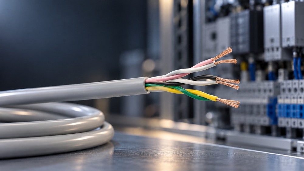
Specify the number of independent pairs, not only the total core count. A four-core cable may be manufactured as two defined pairs, one star-quad, or four cores without controlled pairing; those constructions are not interchangeable.
Multi-pair cables may use different twist lay lengths to reduce crosstalk between adjacent pairs. During installation, preserve the manufacturer's pair identification and keep the twist as close as practical to the terminal. Do not split a circuit across conductors from different pairs simply to simplify colour matching.
Where a drain wire or shield is present, verify its termination method and whether the shield is overall or individual to each pair. Also confirm that glands, connectors, and cabinet entry hardware maintain the intended EMC connection.
Questions to answer before ordering
- What signal or physical-layer standard will the cable carry?
- Is the circuit balanced, differential, single-ended, or current-loop based?
- How many independent pairs are required, and how must they be identified?
- Are individual-pair shields, an overall shield, or both required?
- What conductor material, size, loop resistance, capacitance, impedance, and attenuation limits apply?
- What route length, data rate, termination, and topology are specified?
- Which motors, drives, power conductors, contactors, or radio-frequency sources share the environment?
- What shield bonding and equipotential-bonding method does the connected equipment require?
- Is the cable fixed, occasionally moved, or continuously flexed?
- What temperature, oil, chemical, UV, moisture, fire-performance, approval, and installation requirements apply?
Common mistakes
- Assigning the outgoing conductor to one pair and the return conductor to another.
- Untwisting a long section at a terminal, reducing pair balance at the point of connection.
- Assuming an overall shield makes pair twisting unnecessary for every signal.
- Applying the same shield-grounding rule to every frequency range and installation.
- Using ordinary copper control cable as thermocouple extension cable.
- Using generic twisted-pair cable for HART, RS-485, CAN, PROFIBUS, or industrial Ethernet without verifying the required electrical characteristics.
- Counting cores without confirming the cable's actual pair construction and identification.
- Treating “flexible” as evidence of drag-chain or continuous-flex life.
Information needed for a ZION recommendation
Provide the signal type or protocol, circuit diagram, pair count, conductor size, route length, data rate where applicable, source and load information, interference sources, shielding preference, termination method, movement duty, environment, destination market, and required standards. ZION can then compare available LiYY TP, LiYCY TP, or other suitable part-number data against the application.
Frequently asked questions
Is twisted pair the same as shielded cable?
No. Twisting improves balance and reduces the effective signal-loop area. A shield is a conductive layer used to reduce electromagnetic coupling. A cable may be twisted and unshielded, shielded without defined pairs, or both twisted and shielded.
Does a shorter cable eliminate the need for twisting?
Not automatically. Signal level, source and load balance, equipment design, routing, switching speed, and interference strength can matter even on a short run. Follow the connected-equipment instructions.
Can any twisted pair carry RS-485 or PROFIBUS?
No. The cable must meet the physical layer's required impedance, capacitance, attenuation, conductor, shield, length, and installation specifications. Pair twisting alone is not proof of protocol compliance.
Should a cable shield be grounded at one end or both ends?
There is no universal answer. The correct method depends on the equipment, signal frequency, EMC objective, equipotential bonding, ground-potential difference, and safety design. Use the device and system manufacturer's instructions.
Can standard copper twisted pair be used for a thermocouple?
Normally not as a direct substitute for the required thermocouple or extension/compensating conductors. Match the cable material and polarity to the thermocouple type and measurement standard, then address twisting and shielding as additional noise-control measures.
Prepare a part-number-level cable review
Send the signal or protocol, circuit details, pair count, route length, EMC sources, shielding and termination requirements, movement duty, environment, quantities, destination market, and required standards.
Request Project Support



 Fiber Optic Cable
 Fiber Optic Tools
 Ethernet Cable
 Coaxial Cable
 Fire & Security Cable
 Voice, Audio & Video
 Power & Control Cable