
The same basic handling rules still apply, but connector layouts, ribbon constructions, and equipment interfaces vary. A cable described simply as “MPO” or “suitable for 800G” does not provide enough information to establish compatibility.
This guide covers ten installation mistakes in data centers, equipment rooms, and optical distribution frames (ODFs). The ribbon and splicing sections apply where field splicing is part of the design; fully preterminated installations may not need those steps. Set handling limits and acceptance procedures from the specific product instructions and the project specification before work starts.
1. Applying Pulling Force to the Wrong Part of the Assembly
Connectors and breakout legs are not pulling points unless the assembly manufacturer explicitly provides an approved pulling arrangement for them. Loading these parts can damage the assembly even if its outer jacket appears intact.
Use the specified pulling eye, grip, or protective pulling enclosure and observe the assembly's maximum installation tension. Do not assume that the jacket is an approved pulling point. Stop and investigate if resistance increases unexpectedly. FOA installation guidance
Before pulling, record the approved attachment method and tension limit, and check that the pulling enclosure can pass through the planned route. After placement, secure the cable at the enclosure's designated strain-relief points so its weight does not hang from connectors or exposed fiber groups.
2. Using One Bend-Radius Rule for Every Cable
Check the manufacturer's minimum bend radius both during installation under tension and after installation. A familiar cable-diameter multiplier is not a substitute for the product specification, and radius must not be confused with diameter. FOA installation guidance
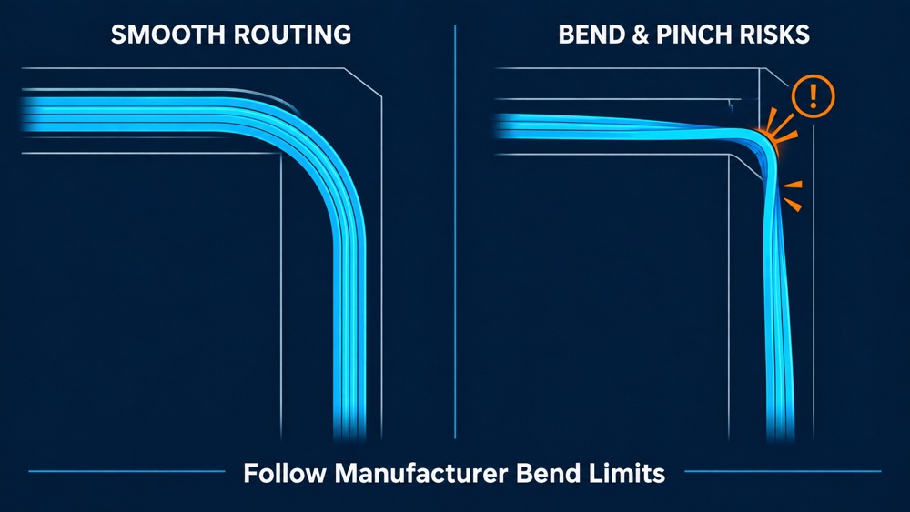
Review corners, rack entries, breakout transitions, and the rear of modules. Move drawers through their intended service travel and inspect the final closed position for pinching, tension, or sharp bends. Bend-insensitive fiber does not remove the need to follow the finished cable assembly's mechanical limits.
3. Leaving Slack Without a Storage or Service Plan
Extra length should have a defined purpose. Excess cable can obstruct ports and trays, while insufficient service allowance can make repairs or drawer movement difficult.
For planning, separate the allowances by function:
- Backbone service slack: length reserved for the agreed repair or rerouting strategy.
- Splice slack: length needed for tray routing and possible resplicing.
- Movement allowance: length needed for a drawer or movable module.
- Patch-cord allowance: length matched to the actual route between ports.
These are planning categories, not standardized slack lengths. Assign a storage location before ordering cable. Follow the enclosure's routing and capacity instructions, and check whether the required slack can be retrieved without disturbing unrelated connections. Do not judge cable management by appearance alone.
4. Checking the Connector Name but Missing Interface Compatibility and Polarity
Matching connector names does not establish a working optical path. For an MPO assembly, verify the fiber-position layout, populated positions, pinned or unpinned configuration, keying, polish, and end-to-end mapping. Two mating MPO connectors require compatible guide-pin and guide-hole arrangements. FOA MPO guidance
Check the exact transceiver part number. For example, Cisco's OSFP 800G portfolio includes dual MPO-12 APC and MPO-16 APC interfaces; it also includes dual duplex LC UPC interfaces. Some of its multimode modules require APC MPO connections. These examples show why neither speed nor fiber type alone determines the connector configuration. Cisco OSFP 800G data sheet
Do not mate APC and flat-polished interfaces. Identify interfaces from product documentation, not housing color alone.
Prepare an end-to-end fiber map covering MPO trunks, modules, adapters, and patch cords. For parallel optics, identify the required transmit and receive lanes and every breakout destination. An A, B, or C polarity designation for one assembly does not prove that the complete channel has the intended mapping.
Record and verify any change made during commissioning, including field changes to configurable connectors. An undocumented patch-cord swap is not a maintainable solution.
5. Assuming a New or Capped Connector Is Clean
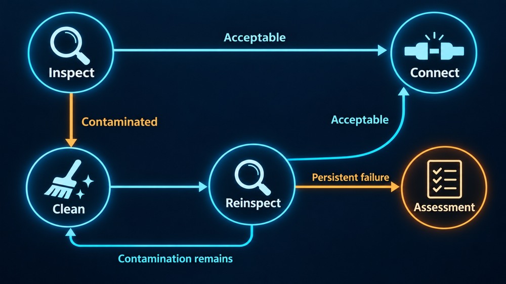
A protective cap does not guarantee cleanliness. Inspect both mating end faces before connection, including the connector behind a panel adapter. If contamination is present, clean with a method approved for that interface and inspect again before mating. Apply the same process to test cords and instrument interfaces. FOA inspection guidance
Use an inspection tip and analysis profile appropriate to the connector and the project's acceptance criteria. For MPO connectors, inspect the fiber end faces and the rectangular ferrule surface for contamination; checking only the fiber positions is incomplete. IEC 61300-3-35:2022 explicitly addresses inspection beyond the fiber zones. IEC 61300-3-35:2022
Keep the sequence consistent: inspect, clean if needed, reinspect, then connect. Follow the equipment manufacturer's inspection and cleaning procedure for transceiver ports.
6. Treating Connector Damage as a Cleaning Problem
Cleaning removes contamination; it does not repair a chipped ferrule, broken latch, or damaged alignment feature. Follow the manufacturer's release procedure for the connector housing, latch, or pull tab. Do not disconnect a connector by pulling its cable.
If appropriate cleaning does not resolve an inspection failure, isolate the assembly for assessment instead of repeatedly cleaning and mating it. Distinguish removable contamination, mechanical damage, and an image-analysis failure before deciding on replacement.
Visual inspection and optical testing serve different purposes. IEC 61300-3-35:2022 states that visual inspection does not replace attenuation or return-loss measurements and cautions against rejecting a connector solely because it fails visual inspection. Resolve persistent failures through the agreed acceptance process, considering optical performance and manufacturer guidance. This does not justify mating a contaminated or mechanically damaged connector. IEC 61300-3-35:2022
7. Routing Ribbon Fiber Without Checking Construction and Tool Compatibility
Conventional bonded ribbons and flexible or rollable ribbon products should not automatically receive the same preparation and routing treatment. Confirm the ribbon construction, fiber identification, coating diameter, fiber pitch, and manufacturer-approved handling method.
Tool compatibility depends on the exact combination of ribbon, holders, stripper, cleaver, and splicer. Do not infer compatibility from fiber count or a single diameter value. For example, Corning documents compatibility with both 200 µm and 250 µm splicers for its Flow Ribbon product; that is a product-specific statement, not a rule for every flexible ribbon. Corning Flow Ribbon brochure
Maintain the specified fiber order through preparation, splicing, and tray routing. Complete one representative tray before repeating the process. Check group identification, entry protection, splice-sleeve fit, routing transitions, and clearance under the cover. Verify that the selected tray and sleeve holders accommodate the actual ribbon and splice protectors.
8. Accepting the Splicer's Estimated Loss as the Final Result
A fusion splicer's loss estimate is useful process feedback, but it is not an acceptance measurement of the installed fiber. Cleanliness, cleave quality, placement, and the selected splice program affect the result. Use the manufacturer's equipment checks and calibration procedure, and review individual-fiber warnings where the splicer provides them. FOA fusion-splicing guidance
Complete splice protection and tray routing before final optical testing. Record any resplicing against the correct cable, ribbon, and fiber identifiers.
Where individual splice loss must be evaluated with an OTDR, agree on the measurement procedure. Differences in backscatter characteristics can make a splice appear to have unusually low loss or even apparent gain in one direction. Bidirectional analysis helps account for that effect. Launch and receive fibers and suitable instrument settings are also needed to characterize the relevant events. OTDR characterization complements the specified end-to-end insertion-loss test. Fluke Networks: OLTS and OTDR testing strategy
9. Tightening Cable Bundles and Overlooking Service Access
Use restraints that support the cable without compressing or deforming its jacket. Follow the cable and enclosure manufacturers' fastening instructions. FOA installation guidance
Check maintainability on a representative populated panel:
- Can a technician read the identifier and release the intended connector?
- Can the inspection probe and cleaning tool reach the port?
- Can the drawer complete its normal service travel without loading cables?
- Does the closed door clear patch cords and connector boots?
- Can one patch cord be replaced without shifting a large bundle?
Repeat this review for the intended final loading, not only a nearly empty panel. Front-panel port count does not establish usable capacity once rear routing, cable entry, and maintenance access are considered.
10. Handing Over the Installation Without Defined Acceptance Tests and Records
A link coming up does not establish that the installation meets its acceptance requirements. Agree on the test scope and pass/fail limits before testing.
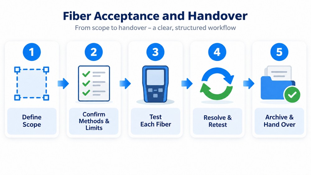
Distinguish the installed link from the complete channel, including equipment cords. The design must satisfy the applicable cabling requirements and the target optical application's channel limits. A component-based loss calculation alone does not establish suitability for a particular transceiver. Check the relevant interface specification for insertion loss, reach, and any additional optical constraints. Cisco QSFP-DD800 data sheet
Measure insertion loss using an appropriate source and power meter or optical loss test set (OLTS). Use compatible, verified reference cords and the reference method specified for the test configuration. Record which connections are included in the measurement; results obtained with different reference arrangements should not be compared without accounting for that difference. FOA insertion-loss testing guidance
For multimode testing, control the launch condition, including encircled flux (EF) where required by the applicable procedure. EF describes the light distribution delivered into the fiber and helps reduce variation between measurements. Fluke Networks: encircled flux
Use the project's specified wavelengths, directions, and test methods. Relevant references include IEC 61280-4-1 for installed multimode attenuation measurement and IEC 61280-4-2 for installed single-mode attenuation and optical return-loss measurement. Apply the edition and amendments required by the project. Include OTDR and other measurements where specified. IEC multimode standard, IEC single-mode standard
Use consistent identifiers to connect the physical installation with its records:
| Handover item | Information to retain |
|---|---|
| Link identity | Cable and fiber IDs, with both rack and port locations |
| Connection mapping | Fiber positions, polarity, breakout destinations, and splice assignments |
| Test configuration | Measurement boundary, wavelengths, directions, reference method, and launch conditions where applicable |
| Acceptance basis | Applicable specification and edition, limits, and target interface requirements |
| Results | Required per-fiber results, pass/fail status, instrument identification, and corrective-action records |
| Final configuration | As-built drawings, patch records, and approved changes |
Include all fibers required by the handover specification, including spare fibers where specified. After resplicing, replacing a component, or changing a connection, update the affected records and repeat the relevant tests.
Bring Installation Requirements into the Purchasing Brief
Before ordering, document cable handling limits, routed lengths, connector configurations, fiber maps, labeling, enclosure compatibility, and test deliverables. Ask for the documentation that allows the supplied components to be checked against those requirements.
When discussing a project with ZION, provide the rack layout, cable routes, fiber count, exact equipment interface or transceiver part numbers, and acceptance criteria. Request product-specific handling instructions, connector and polarity drawings, and applicable factory test records for the proposed items. These details give both parties a concrete basis for checking the proposed configuration before installation.
Prepare Your Fiber Installation Brief
Send the rack layout, cable routes, fiber counts, equipment part numbers, and acceptance criteria when discussing the proposed components with ZION.
Request Project Support


