MPO Patch Cords for High-Density Data Center Fiber Patching | ZION
MPO patch cords are short, pre-terminated multi-fiber jumpers used between panels, cassettes and active equipment in high-density fiber systems. ZION configurations cover OS2, OM3 and OM4 with multiple fiber counts, connector genders, polarity methods and loss grades. Start by matching the installed fiber system and mating interfaces, then confirm polarity, channel loss and routing length.
Which MPO Patch Cord Is Available?
This category contains one configurable MPO patch cord family rather than separate fixed products. Select the required fiber mode, fiber count, connector gender, polarity, loss grade, jacket and length for the actual channel.
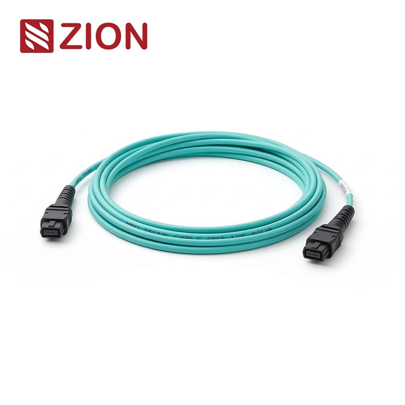
![ZION MPO patch cord in 12F 24F OS2 OM3 and OM4 configurations]()
12F / 24F · OS2 / OM3 / OM4
MPO Patch Cord
A configurable multi-fiber jumper for short panel, cassette and equipment connections. Consider it when density and pre-termination matter; confirm fiber count, gender, polarity, loss grade, 3.0 mm LSZH construction and length before ordering.
View Product Details → How Do I Choose an MPO Patch Cord?
Define six items before comparing prices: fiber type, fiber count, connector gender, polarity, loss grade and target length. These choices determine whether the cord mates correctly and whether the completed channel stays within its optical budget.
OS2, OM3 or OM4?
Match the installed fiber and optic. OS2 is single-mode; OM3 and OM4 are multimode. Do not mix modes within a channel, and do not select OM4 only because it sounds newer when the installed system is OM3.
8F, 12F, 16F or 24F?
Choose the fiber count from the connector interface, active lane map and panel plan. A higher count increases density only when the equipment and cable-management design can use it; confirm the selected version at RFQ stage.
Female or male?
Connector gender indicates whether alignment pins are present. Confirm both mating sides before ordering: two pinned plugs cannot mate correctly, and two unpinned plugs cannot align without a pinned mating interface.
Type A, B or C?
Polarity controls how transmit and receive positions map through the channel. Select Type A, Type B or Type C only within a documented end-to-end method that includes every trunk, cassette, adapter and patch cord.
Standard or low loss?
Use the complete channel budget to decide. Low loss becomes more valuable when the route contains multiple mating pairs, cassettes or future reconfiguration; require the quoted maximum loss and assembly test report for the selected version.
Standard or custom length?
Measure the real cabinet route, including bend control and service access. Custom length reduces slack and improves airflow visibility, while project labels make later moves, adds and changes easier to manage.
Which Configuration Should I Shortlist?
Use these configurations as practical starting points, then confirm the exact mating interfaces and channel design. They are configurable versions within the same MPO patch cord family, not separate fixed products.
| Configuration | Fiber | Connector | Loss Grade | Best For |
|---|
| Standard OM3 12F | OM3, 12 fibers | MPO female-to-female | Standard loss | Mainstream data center patching |
| Standard OM4 12F | OM4, 12 fibers | MPO female-to-female | Standard loss | OM4 multimode systems |
| High-Density OM4 24F | OM4, 24 fibers | MPO female-to-female | Standard or low loss | Higher density in limited rack space |
| Low-Loss OS2 12F | OS2, 12 fibers | MPO female-to-female | Low loss | Single-mode structured links |
| Low-Loss OS2 24F | OS2, 24 fibers | MPO female-to-female | Low loss | High-density single-mode patching |
| Custom-Length MPO | OS2, OM3 or OM4; 12F or 24F | Female or male | Standard or low loss | Clean routing and project labeling |
What Optical Performance Should Be Specified?
Insertion loss must be treated as a version-specific acceptance value, not just a marketing label. The figures below are configuration references for this family; require the selected version's quotation, data sheet and test report to state the applicable maximum.
| Performance Item | Standard-Loss Reference | Low-Loss Reference | What to Confirm |
|---|
| Single-mode insertion loss | Up to 0.75 dB max | Up to 0.35 dB max | Selected OS2 version, polish and test wavelength |
| Multimode insertion loss | Up to 0.60 dB max | Up to 0.35 dB max | Selected OM3/OM4 version and test wavelength |
| Return loss | Mode and polish dependent | Mode and polish dependent | Exact end-face specification and acceptance limit |
Where Are MPO Patch Cords Used?
MPO patch cords fit short, serviceable connections where multi-fiber density is useful. They should not be selected only from Ethernet speed or connector appearance; the optic, active fiber map and mating interfaces still control compatibility.
Panel-to-panel patching
Use 12F or 24F configurations for compact interconnection between distribution fields. Confirm the full polarity path before standardizing the order across multiple cabinets.
Cassette connections
A 12F standard configuration is a practical starting point for cassette-to-cassette patching. Keep lengths disciplined to protect airflow, bend control and front-of-rack access.
Active equipment
Use a direct MPO equipment patch only when the transceiver interface, active fibers, polarity and pinning are confirmed. Some high-speed optics use duplex LC or a different multi-fiber arrangement.
High-density cabinets
Use 24F only when its density gain improves the real layout. Check panel accessibility, pathway fill and cable-management space so higher fiber count does not make maintenance harder.
Custom rack routing
Custom lengths reduce slack and make service paths easier to read. Combine length control with route-based labels, endpoint IDs and packaging by cabinet or installation zone.
What Reduces Cost and Maintenance Risk?
The cheapest unit price does not protect a project from wrong mode, gender, polarity or length. Complete specifications and route-based identification usually save more than a generic cord that requires rework.
Loss margin
Standard loss can suit a simple channel; low loss protects margin in denser paths. Count every mating pair and use the worst-case budget before paying for or rejecting the lower-loss option.
Cable length
Generic lengths may create slack, clutter and hidden bend stress. A measured route and controlled service loop improve cabinet visibility without making the cord too short for safe handling.
Labels and records
Use endpoint, route, polarity and length identifiers that match drawings and test records. Clear labels reduce fault-tracing time and prevent cords from being returned to the wrong path.
Frequently Asked Questions
What is an MPO patch cord?
It is a short, pre-terminated cable that carries multiple optical fibers through one compact connector. It is commonly used between panels, cassettes and compatible equipment where high density and fast installation matter.
What is the difference between 12F and 24F MPO patch cords?
A 24F cord carries twice as many fibers as a 12F cord in the assembly, but it is useful only when the connector, panel and lane plan support that density. Choose from the actual interface and routing design, not fiber count alone.
Do I need a low-loss MPO patch cord?
Use low loss when the worst-case channel budget requires the extra margin. Multiple panels, cassettes and mating pairs make it more valuable; a short, simple channel may be acceptable with standard loss after calculation and testing.
Can an MPO patch cord connect directly to a transceiver?
Yes, but only when the transceiver uses the same MPO interface and the fiber mode, active positions, polarity, polish and pinning match. The Ethernet speed label alone is not enough to prove compatibility.
Can I mix OM3 and OM4 in one channel?
Do not treat mixed OM3 and OM4 as an OM4 channel. The completed link must be designed and accepted to the performance of its installed components and the selected optic's reach requirements.
Why does MPO connector gender matter?
Gender determines whether alignment pins are present. Correct mating needs one pinned side and one unpinned side, so verify the equipment, adapter or opposing cable before choosing male or female.
RFQ Checklist
If every field is not known yet, provide the transceiver part number, mating equipment and route drawing. These details allow the final MPO configuration to be reviewed before quotation.
Application, transceiver manufacturer and part number, and both mating interfaces
OS2, OM3 or OM4 fiber type and 8F, 12F, 16F or 24F count
MPO connector format, male/female gender, key orientation and UPC/APC polish
Type A, Type B or Type C polarity plus the complete end-to-end lane map
Standard-loss or low-loss grade and maximum accepted insertion loss
3.0 mm LSZH or required jacket, overall length and tolerance
Quantity by configuration, project labels, test report and packaging requirements




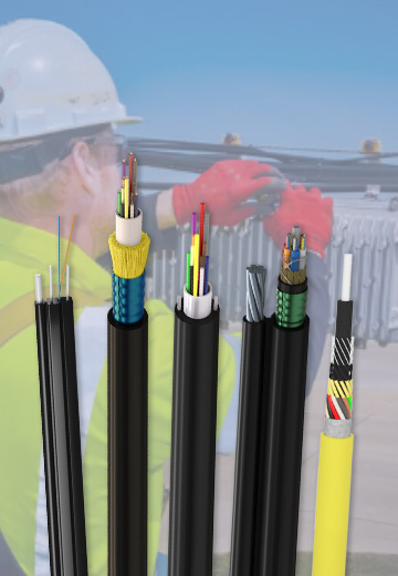 Fiber Optic Cable
 Fiber Optic Tools
 Ethernet Cable
 Coaxial Cable
 Fire & Security Cable
 Voice, Audio & Video
 Power & Control Cable