What Is an Underwater Anti-Interference Optical Fiber Communication System?
An underwater anti-interference optical fiber communication system is a marine data link solution based on optical fiber transmission. In this ZION system, a specially designed optical fiber tube works as the core transmission medium, while underwater optical transceivers and waterproof connectors complete the communication path.
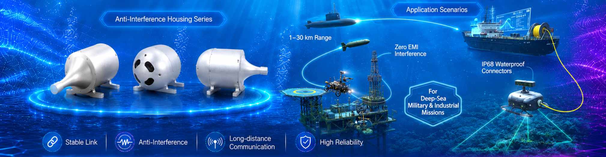
Because the signal is transmitted through optical fiber rather than an electrical conductor, the system is suitable for projects where electromagnetic interference, underwater cable routing and long-distance data communication need to be considered together.
How the Underwater Optical Fiber Link Works
The system can create a wet-to-dry communication path between underwater equipment and a dry-side platform such as a mother ship. The source diagram shows underwater optical transceivers connected through water-tight connectors, splice or junction boxes, FC adapters and 30 km fiber drums.
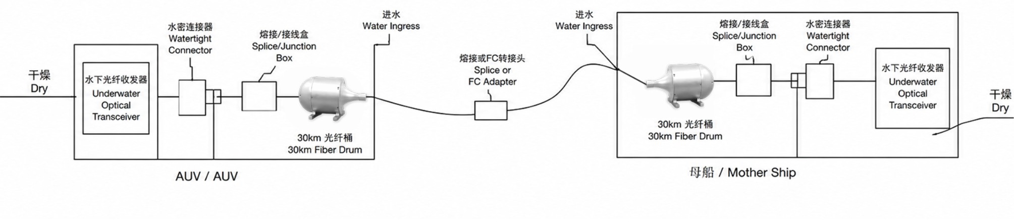
In a typical configuration, the transmitting unit, receiving unit and fiber drum should be matched with the required interface, link distance and mechanical installation conditions. The water-tight connector helps protect the connection where the link passes through the underwater environment.
System Composition
The PDF identifies three main parts of the underwater communication system. Each part serves a different role in building a complete optical communication link.
Provides the ready-to-use optical fiber drum for underwater deployment, with length options from 1 km to 30 km.
Includes transmitting and receiving optical terminal equipment with optical, network and serial port interfaces.
Supports the water-tight wired connection required for underwater optical communication routes.
Core transmission medium: Aramid + PVC sheath with G.657.A2 fiber, providing a stable and reliable data channel with high tensile strength and environmental resilience.
High-Speed Optical Fiber Release Device Specifications
The high-speed optical fiber release device is the deployable fiber element of the system. Its specifications define the link length, cable structure, interface options and environmental operating range.
| Parameter | Value |
|---|---|
| Product Name | High-speed optical fiber release device |
| Length Options | 1 km - 30 km |
| Sheath Material | Aramid + PVC |
| Fiber Type | G.657.A2 |
| Optical Cable Diameter | 0.5 mm / 0.65 mm |
| Unit Weight | 248 g/km / 430 g/km |
| Tensile Strength | >150 N / >200 N |
| Operating Temperature | -40°C to +60°C |
| Optical Interface | FC/UPC or LC/UPC |
| Attenuation Coefficient | ≤0.35 dB/km @ 1310 nm ≤0.25 dB/km @ 1550 nm |
| Can Material | Resin & metallic aluminum |
| Standard Dimensions | 237×180×152 mm (10 km) 300×277×248 mm (20 km) |
| Cable Density | 1.25 g/cm3 / 1.3 g/cm3 |
| Color | Yellowish |
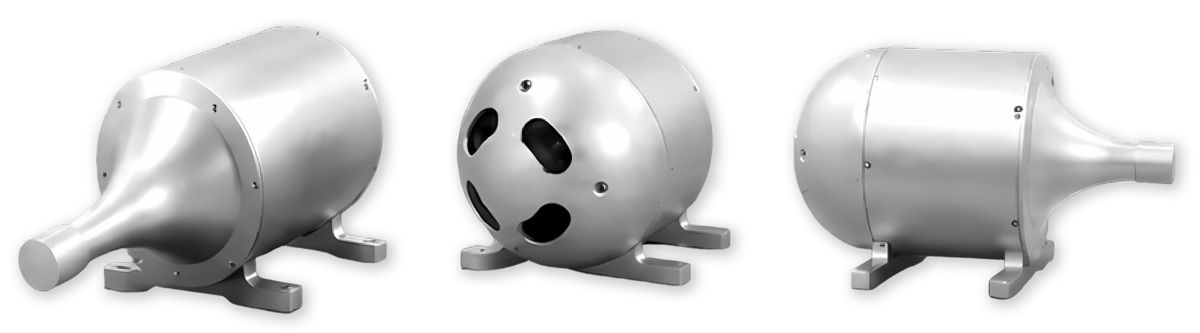
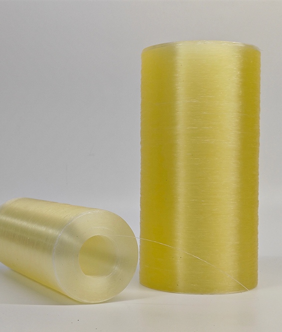 Aramid fiber tube material
 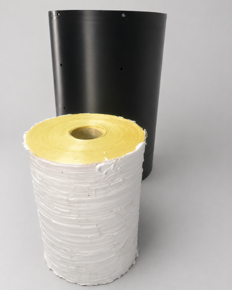 Fiber drum with protective canister
 Optical Transceiver Equipment Specifications
The transmitting and receiving optical terminal equipment convert and carry data across the underwater optical link. The source material lists the same wavelength and interface families for both units.
| Item | Transmitting Unit | Receiving Unit |
|---|---|---|
| Product Name | Transmitting Optical Terminal | Receiving Optical Terminal |
| Wavelength | 1310 nm / 1550 nm | 1310 nm / 1550 nm |
| Interfaces | Optical port (FC), Network port, Serial port | Optical port (FC), Network port, Serial port |
| Connection Type | Water-tight wired connection | Water-tight wired connection |
| Customization | Supported (wavelength, interface type, mechanical design) | |
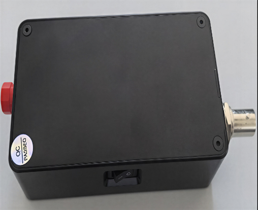 Transmitting optical terminal equipment
 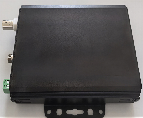 Receiving optical terminal equipment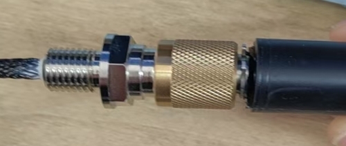
Application Scenarios
The system is intended for marine projects where underwater equipment needs stable, anti-interference data transmission. The PDF lists applications across underwater robotics, observation networks, marine engineering and coastal monitoring.
Selection Factors for Marine Projects
Before discussing a project, confirm the link distance, the underwater device type, the required optical and data interfaces, the connection layout and the mechanical installation conditions. The fiber length, cable diameter, terminal interface and connector design should match the actual deployment path.
Use the 1 km - 30 km length range as the starting point for confirming the required fiber drum configuration.
Confirm whether FC/UPC or LC/UPC optical interface options and terminal data ports match the system design.
Review connector, housing, cable outlet and water-tight wired connection requirements for the installation environment.
FAQ
What is the core transmission medium in this underwater communication system?
The core transmission medium is an aramid and PVC sheath optical fiber tube using G.657.A2 fiber, designed to provide a stable data channel with tensile strength and environmental resilience.
Which length options are shown for the high-speed optical fiber release device?
The source material lists length options from 1 km to 30 km for the high-speed optical fiber release device.
What project information should be confirmed before selecting the system?
Project teams should confirm link distance, underwater equipment type, required interfaces, connector requirements, operating environment, and whether custom wavelength, interface type, or mechanical design is needed.



 Fiber Optic Cable
 Fiber Optic Tools
 Ethernet Cable
 Coaxial Cable
 Fire & Security Cable
 Voice, Audio & Video
 Power & Control Cable