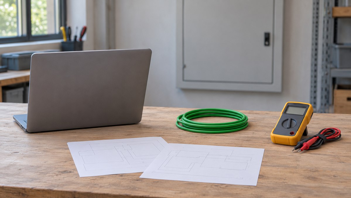
AI-generated conceptual scene; not a wiring or measurement demonstration.
A voltage reading is not a communication test
A DC reading confirms a potential difference at the measurement point. It does not establish that KNX TP telegrams can be exchanged. Computer recognition of an interface also does not prove access to a bus device. Record interface detection, device access and application operation separately.
Identify the correct output
Trace the bus pair to the power supply. Use the exact model’s wiring diagram and terminal markings to distinguish the KNX bus output from an auxiliary DC output. Do not rely on terminal color alone. Check polarity and whether the supply path includes the required choke. An auxiliary output is not automatically a second direct bus output.
Understand the choke
KNX TP carries power and communication over the same pair. A suitable choke passes the DC supply while presenting higher impedance to the communication signal, preventing the supply from effectively shunting telegrams. Some supplies integrate this function; approved arrangements may instead use a separate choke. Follow the manufacturer’s ratings and connections. Do not substitute a generic inductor or bypass the choke.
Start with a controlled test segment
Plan the service interruption and preserve the configuration before changing wiring. Qualified personnel should follow the manufacturer’s isolation procedure when working inside mains-powered enclosures. Begin with the correct supply and interface on one line. Add a configured device, then restore devices or branches progressively. Record the last successful configuration and the change associated with failure. Do not directly join separate lines for convenience.
Check other possible causes
Check supply loading, duplicate individual addresses, addresses inconsistent with the physical line, reversed mainline/subline connections at couplers and unintended interconnections between lines. A correct power output does not exclude these faults. If device access succeeds but an application function fails, investigate configuration rather than assuming a cable fault.
Commissioning handover checklist
Power source: model, manual revision, terminals used and integrated or external choke arrangement.
Line and load: line identifier, drawing revision, device list and documented current requirements.
Measurements: location, polarity, voltage reading, connected load and time. Record communication results separately.
Connections: pair assignments, interface and device addresses, and coupler connections.
Handover: changes made, results, outstanding issues, responsible person and date.
Match the cable to the confirmed design
Review cable construction and installation requirements after confirming power and topology. Consult the ZION KNX cable range at ZION KNX Cable and provide installation conditions, route lengths and quantities. Replacing cable alone cannot correct an inappropriate supply output or address assignment.



 Fiber Optic Cable
 Fiber Optic Tools
 Ethernet Cable
 Coaxial Cable
 Fire & Security Cable
 Voice, Audio & Video
 Power & Control Cable