Why the MMR Is Not a Normal Equipment Room
A carrier-neutral data center meet-me room is the boundary between carriers, tenants, cloud connectivity and campus backbone routes. A medium decision that works for an internal server-room link may not fit a carrier handoff or a future cross-building service.
OS2 is often the natural foundation for carrier handoff, DCI and longer metro or campus extension. OM4 can still be valid for controlled short-reach internal links when both ends, optics and life-cycle costs are clearly defined.
Draw the Service Boundary First
Break the path into OSP entrance, carrier demarcation, MMR frame, cross-connect, tenant or network room and active equipment. For each segment, mark asset owner, interface, maximum route length, connection points, test responsibility and whether intermediate patching is allowed.
If the carrier delivers single-mode service or the path may later extend to metro or long-haul networks, OS2 usually reduces future constraints. If the link stays inside the facility and the transceiver plan is explicitly multimode, OM4 may be practical.

Reach: Use Route Length, Not Floor-Plan Distance
Measure the routed path, including entrance bends, diverse route detours, risers, tray routing, service slack and future migration allowance. Then calculate the loss budget across connectors, adapters, splices and operational margin.
Do not publish a single reach rule without naming the Ethernet application, transceiver specification, connector count and acceptable link loss. Multimode fiber remains useful in short data center applications, but the final reach is application-specific.
Fiber Count and Polarity
MMR fiber count is not current port count multiplied by two. Separate carrier interconnects, tenant cross-connects, DCI, management, dark-fiber offerings, monitoring, spares and growth.
Future movement from duplex LC toward MPO/MTP, breakout or WDM architectures affects fiber count, polarity and patching modules. Decide the modular patching strategy before adding more loose jumpers.

Patching and Operations
MMRs change often. Evaluate ODF or patch-panel density, front access, bend radius, adapter replacement, polarity control, patch-cord pathways, readable labeling and maintenance isolation.
Every cross-connect should have a unique circuit ID tied to A-end, B-end, fiber, panel port, service state and test file. Labels should be approved before installation, not improvised during commissioning.
Route Diversity
A primary and backup link are not truly diverse just because they are separate circuits. Verify separate entrances, conduits, trays, splice points, ODF zones and known physical risk points.
Two OS2 cables that share the same handhole, wall penetration or tray section still carry common-mode risk. Treat route diversity as a field-verified condition rather than a drawing convention.

Decision Matrix
| Decision factor | OS2 tendency | OM4 tendency | Must verify |
|---|---|---|---|
| Service boundary | Carrier, DCI and campus or metro extension | Controlled internal short reach | Equipment and optics owner |
| Reach | Longer distance and more future margin | Known short path | Application rate, optics data sheet and loss budget |
| Optics | Single-mode transceivers | VCSEL multimode transceivers | Whole-life module cost |
| Patching | LC, MPO/MTP and WDM can be planned | LC/MPO high-density links are common | Polarity, cleaning, end-face and MAC process |
| Future use | Dark fiber, carrier handoff and DCI flexibility | Economical within a fixed short-reach architecture | Five-to-ten-year migration route |
Related ZION Resources
Use this ZION resource when the project needs matching products, cable selection context or a clearer passive BOM.
Use this ZION resource when the project needs matching products, cable selection context or a clearer passive BOM.
Use this ZION resource when the project needs matching products, cable selection context or a clearer passive BOM.
Use this ZION resource when the project needs matching products, cable selection context or a clearer passive BOM.
Sources and Standards
- AFR-IX Telecom website
- Raxio Angola carrier-neutral Tier III data centre page
- Corning meet-me-room application page
- CommScope meet-me-room and fiber entrance page
FAQ
Is OS2 always better than OM4 in an MMR?
No. OS2 is often more flexible for carrier and long-reach boundaries, but OM4 can be suitable for controlled short links with known multimode optics.
What should be measured before choosing the fiber type?
Measure routed distance, connection count, adapter and splice points, service slack, planned transceiver type and future migration requirements.
Can OS2 and OM4 coexist in the same MMR?
Yes, but the patching, labeling, color management, port database and test files must make the media boundary clear for operations teams.



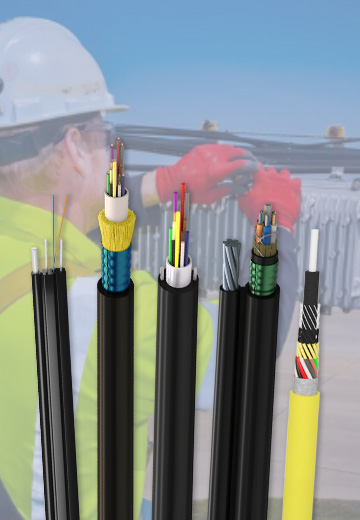 Fiber Optic Cable
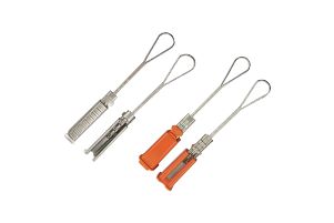 Fiber Optic Tools
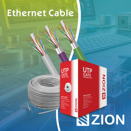 Ethernet Cable
 Coaxial Cable
 Fire & Security Cable
 Voice, Audio & Video
 Power & Control Cable