
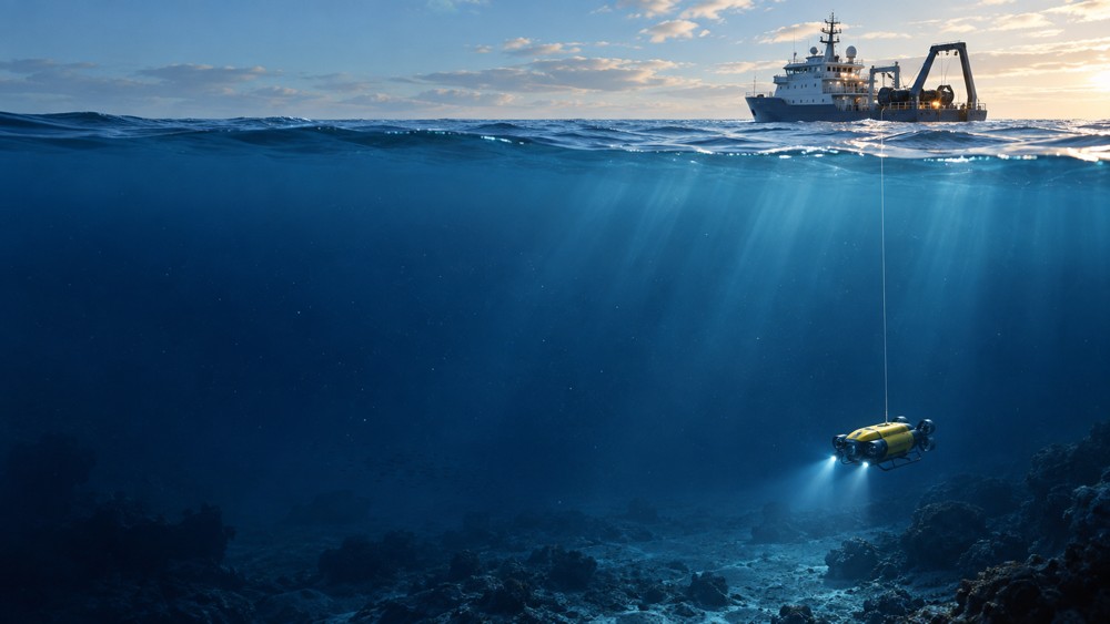
Three Fiber-Link Architectures That Should Not Be Confused
A conventional work-class ROV, an autonomous vehicle and a hybrid microtethered vehicle place very different demands on the cable system. The same word—“tether”—does not mean the cable performs the same functions in each case.
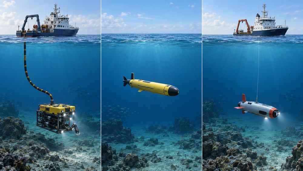
A deck winch and armored composite umbilical commonly deliver power and data and may carry the mechanical load. Deepwater systems may add a tether management system (TMS) or depressor with a shorter, more flexible vehicle tether.
A typical AUV follows a pre-programmed mission using onboard energy and autonomy. It may use acoustic communications for low-rate updates and transfer the main mission data after recovery.
The vehicle carries its own batteries while a thin, low-drag fiber provides real-time video, commands and sensor data. The link needs a separate loss-of-link and vehicle-recovery strategy.
WHOI's Nereid Under Ice is a documented hybrid example. It carries a 20 km, 250 µm fiber-optic microtether for data and control while onboard batteries power the vehicle. This validates the general architecture; the operating envelope of any other cable still depends on its own depth, payout, tension, bend and termination data.
Where the ZION Deployable Fiber Spool Fits
The ZION underwater fiber-optic spool is a deployable micro-fiber data-link component. The current public specifications list 1–30 km lengths, G.657.A2 single-mode fiber and finished cable diameters of 0.5 mm and 0.65 mm.
| Parameter | Published nominal value | Engineering interpretation |
|---|---|---|
| Length | 1–30 km | Spool supply length, not a verified mission radius. |
| Fiber category | G.657.A2 | Bend-insensitive single-mode fiber; the finished cable and payout assembly still require defined static and dynamic bend limits. |
| Cable diameter | 0.5 mm / 0.65 mm | Lightweight microcable rather than a conventional powered, load-bearing umbilical. |
| Cable mass | 248 g/km / 430 g/km | Thirty kilometres of cable is approximately 7.44 kg or 12.9 kg, excluding the canister, termination and housing. |
| Listed tensile strength | >150 N / >200 N | Approximately 15.3 kgf / 20.4 kgf. A working load, safety factor and termination strength are still needed; these values are not vehicle lifting ratings. |
| Attenuation | ≤0.35 dB/km at 1310 nm; ≤0.25 dB/km at 1550 nm | Cable attenuation only. Connections, bending, deployment effects and engineering margin must be added. |
| Listed density | 1.25 / 1.3 g/cm³ | Higher than typical seawater density, so the listed bare cable construction is not neutrally buoyant. |
Supplier-published values are inputs to the system design. Project documentation should connect each value to a configuration, test method and acceptance condition. G.657.A2 defines a fiber category; operating depth, hydrostatic pressure, abrasion resistance and dynamic payout performance apply to the finished assembly and require separate qualification.
A 30 km Link Still Requires an Optical Power Budget
Using the maximum attenuation values on the product page, the fiber-only loss for a 30 km one-way path can be estimated directly.
This is the maximum published cable attenuation for the 30 km fiber length before connection and system penalties are added.
The lower fiber attenuation does not by itself guarantee operation; the selected transceivers and complete channel still have to close the budget.
Total channel loss must include wet or pressure-boundary connections, splices, macro- and microbending, transmitter tolerance, temperature, aging, deployment-induced change and an engineering margin. Receiver sensitivity defines the minimum acceptable input, while receiver overload also matters on shorter configurations.
A drawing with one 30 km spool at each end does not automatically establish a 60 km link. The lengths can be added only when both fibers form a verified series path and the intermediate connection, deployment topology, total attenuation, dispersion and transceiver budget all meet the requirement. A two-ended payout arrangement also needs a defined meeting or connection method.
Bidirectional Communication Requires More Than a Wavelength Label
“1310 nm or 1550 nm” does not define an interoperable link. An interface control document should cover the optical, service, electrical and mechanical interfaces at both ends.
Confirm fiber count, single-fiber BiDi or dual-fiber operation, each end's transmit and receive wavelength, launch power, receiver sensitivity, overload level and allowed channel loss.
Define Ethernet rate or serial electrical standard, protocol, line coding, upstream and downstream bandwidth, video format, target error rate and maximum latency.
Confirm underwater-terminal voltage, peak power, grounding and start-up behavior together with connector model, polish, pressure boundary, strain relief and installation envelope.
Optical fiber carries light, not electrical power. Without copper conductors, the underwater terminal, cameras, sensors and propulsion system require onboard batteries or another independent supply. FC/UPC and LC/UPC describe connector families and polish; they do not define the communications protocol.
Payout Architecture Determines the Mechanical Risk
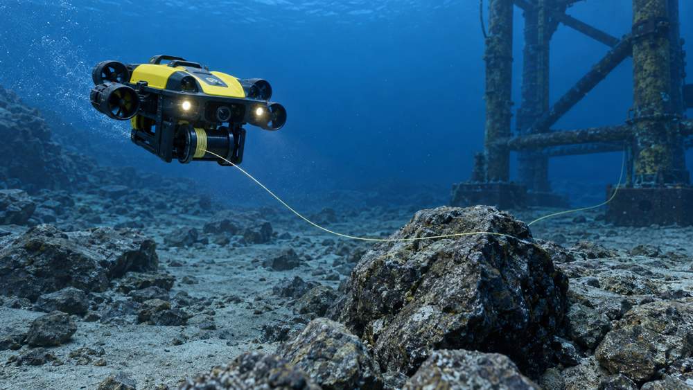
A spool may travel with the vehicle, remain at a fixed endpoint or form part of a qualified two-ended deployment. The selected arrangement changes cable tension, hydrodynamic drag, snag exposure, route reserve and recovery logic.
- Keep payout tension below the documented allowable working tension and include dynamic shock margin.
- Evaluate vehicle speed, turning radius, currents, drag and lateral loading.
- Define outlet guidance, finished-cable bend radius, permitted payout direction and maximum payout speed.
- Review abrasion, snagging and entanglement around seabed features, structures, propellers and thrusters.
- State whether the fiber is abandoned, recovered or redeployed, and how the vehicle itself is recovered.
- Program hold, surface, return or ballast-release behavior for a break, jam or end-of-spool event.
A microcable reduces drag but has less mechanical protection than a conventional umbilical. Vehicle lifting or safety-recovery service requires a separately defined load path, working-load limit, safety factor and qualified termination.
Information Required for an Engineering RFQ
A useful request for quotation should define the mission and system boundary before asking for a spool length or connector option. This allows the microcable, optical terminals, pressure interfaces and vehicle behavior to be reviewed as one link.
- Platform: ROV, AUV, HROV, UUV or fixed observatory.
- Mission: operating depth, route, horizontal range, speed, current, sea state and seabed or structure environment.
- Power: onboard source, continuous and peak loads, voltage range and any surface-power requirement.
- Mechanical duty: whether the line carries load or supports recovery, with the required allowable working load.
- Deployment: single-use, recoverable or reusable operation, spool location, payout direction and payout speed.
- Optical configuration: fiber count, BiDi or dual-fiber topology, wavelengths, connector types and pressure-boundary feedthrough.
- Services: interfaces, protocols, data rates, video formats, bandwidth direction and maximum latency.
- Power budget: transmitter and receiver data plus connector, splice, dynamic-loss and engineering margins.
- Fault response: autonomous behavior and recovery process after loss of link.
- Acceptance: pressure, temperature, tensile, bending, abrasion, salt-fog, payout and end-to-end functional tests.
For a more detailed procurement sequence, use the Underwater Fiber Optic Spool Selection Guide. For signal conversion, sealing and link-operation details, see How Underwater Fiber-Optic Communication Systems Work.
Frequently Asked Questions
Can a thin deployable fiber spool replace a conventional ROV umbilical?
A conventional ROV umbilical may provide electrical power, mechanical strength and data transmission. A thin microcable carries optical data only unless the complete system includes separate conductors and a qualified load-bearing structure. A battery-powered vehicle and a separate recovery method are normally required for a microtether architecture.
Does a 30 km spool guarantee a 30 km operational link?
No. Route geometry, depth, slack, obstacle detours and engineering reserve consume deployed length. Optical operation also depends on the complete power budget, including cable, connector, splice, bend, temperature and deployment losses.
Does G.657.A2 define the underwater depth rating of the cable?
No. G.657.A2 defines bend-insensitive single-mode fiber characteristics. The operating depth and pressure rating must be established for the finished cable, terminations, connectors, canister and complete assembly through project-specific specifications and tests.
What information is needed before requesting a quotation?
Provide the platform type, route and operating depth, onboard power, required length, deployment and recovery method, fiber topology, wavelengths, connectors, data interfaces and rates, transceiver power budget, payout conditions, loss-of-link behavior, quantity and acceptance tests.
Technical References
- ZION Underwater Fiber Optic Spool for ROV/UUV Communication
- WHOI: Nereid Under Ice
- WHOI: Miles Under the Sea, Hanging on by Hair-Thin Fiber
- NOAA Ocean Exploration: Remotely Operated Vehicles
- Nautilus Live: ROV Hercules
- ITU-T G.657: Bend-Insensitive Single-Mode Optical Fiber and Cable
Prepare the Complete Underwater Fiber-Link Requirement
Submit the vehicle type, planned route, operating depth, onboard power, required interfaces, payout conditions, installation envelope, quantity and acceptance tests so the spool, microcable, terminals and connectors can be reviewed together.
Request Project Support


