Quick Answer
5G networks need more fiber because radio capacity is useful only when the transport network can carry the resulting traffic. Compared with a network based mainly on widely spaced macro towers, a denser architecture may include:
- upgraded macro sites with higher-capacity backhaul;
- centralized or distributed RAN locations requiring fronthaul or midhaul;
- indoor and outdoor DAS remote units;
- small cells installed on poles, rooftops, streets and inside buildings;
- edge cabinets and aggregation points closer to users; and
- additional demarcation, splicing and distribution points throughout the route.
Not every radio needs a dedicated fiber pair, and not every site will use fiber for the entire path. Microwave, millimeter-wave and other wireless backhaul technologies remain useful. Nevertheless, capacity, latency, distance, interference immunity and upgrade potential make fiber a common foundation for high-performance, high-density wireless networks.

Recent Market Signals: Wireless Expansion Is Becoming More Fiber-Rich
Recent announcements across distribution, stadiums and airports show the same infrastructure pattern from different angles. Higher-capacity wireless service is being planned together with fiber backbones, distributed radio locations, pathways, enclosures, power and long-term operations—not as a radio-only upgrade.
On September 2, 2026, Clearfield announced a distribution alliance with WAV for U.S. and Canadian wireless customers. The scope covers metro core, wireless backhaul, indoor and outdoor DAS, and small cells, together with fiber connectivity, pathways, enclosures, cabinets, power and active equipment. The signal for buyers is that a deployable wireless site requires an integrated physical-infrastructure package rather than cable purchased in isolation.
In March 2025, Major League Soccer named Boldyn Networks its official DAS partner across league venues. The announced approach combines neutral-host DAS, Wi-Fi, private networks and sensor networks, with a deep fiber backbone supporting the converged environment. This illustrates how venue 5G can increase both radio density and the number of managed optical distribution points behind it.
In February 2025, Boldyn announced a permanent, multi-operator 5G network for Silverstone using a hybrid active DAS. The deployment spans 25 locations, 57 high-capacity sectors and 87 DAS zones. Moving from seasonal temporary systems to a permanent architecture turns a coverage project into a repeatable network of head-end, distribution, remote-unit, power and maintenance interfaces.
In January 2026, Seattle-Tacoma International Airport selected Boldyn to design, build and manage a neutral-host 5G DAS covering terminals, concourses, tarmac, parking and rental-car facilities. The scale and variety of spaces demonstrate why large DAS projects require segmented pathways, distributed equipment locations, environmental transitions and documented service access.
These cases differ in ownership model and setting, but their procurement implications converge. More radio endpoints require more defined A-end and Z-end connections, more distribution and demarcation locations, more coordinated power and enclosure decisions, and more acceptance records. The exact fiber count still depends on the selected active architecture; the market signal is the growth in physical interfaces and repeatable site packages.
Sources: Clearfield and WAV, MLS and Boldyn, Silverstone 5G DAS, and Seattle-Tacoma Airport 5G DAS.
More Radios Do Not Mean Less Fiber
The word “wireless” describes the final connection between a user device and a radio. It does not describe the complete path taken by the data.
Only the first segment is necessarily wireless. Once traffic reaches a radio site, it must be aggregated and transported. As the number of sites increases, the transport network must serve more endpoints, often with higher aggregate capacity and stricter latency or synchronization requirements.
Network densification therefore changes passive infrastructure. It may require more feeder routes, branch points, handholes, closures, terminals, ODF ports, patch cords and test records, even when the geographic service area stays the same.
Where Fiber Sits in a 5G Wireless Network
The terms backhaul, midhaul and fronthaul are sometimes used loosely. For procurement, define the actual endpoints instead of relying only on a label.

| Network segment | Simplified function | Typical endpoints | Passive fiber considerations |
|---|---|---|---|
| Metro or core transport | Aggregates traffic toward regional and core networks | Hub, central office, data center or core PoP | High fiber density, route diversity, scalable ODF capacity and documented patching |
| Backhaul | Connects a cell site or RAN location to aggregation or core | Macro tower, small cell hub or edge cabinet to aggregation node | Outdoor cable, closures, site ODF, protection route and end-to-end loss testing |
| Midhaul | Connects distributed and centralized RAN functions | Distributed unit to centralized unit | Defined optical interface, latency budget, fiber availability and resilient topology |
| Fronthaul | Connects radio-related units to distributed or baseband processing | Radio unit to distributed or baseband unit | Fiber count, connector type, environmental protection, bend control and repeatability |
| DAS distribution | Extends signals from a head-end or hub toward remote units | DAS head-end to indoor or outdoor remotes | Building pathways, riser/plenum requirements, compact distribution and service access |
The exact architecture varies by operator and equipment platform. A buyer should state both ends of every passive link, the optical interface at each end and who is responsible for final patching.
How 5G Deployment Types Increase Fiber Demand
1. Macro-Site Upgrades Increase Backhaul Demand
5G does not eliminate macro towers. Operators frequently reuse and upgrade existing sites by adding spectrum bands, radios, antennas and baseband capacity. Even if the number of towers remains unchanged, the traffic leaving each upgraded site can rise substantially.
An older microwave link may need additional channels, a higher-capacity replacement, a shorter-hop design or migration to fiber. Where fiber already reaches the tower, the project may still require new optical interfaces, additional fibers, route protection or upgraded site termination.
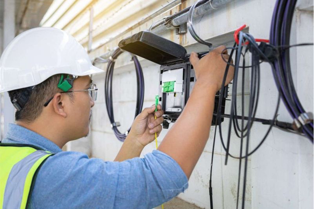
“Fiberizing a tower” means more than ordering one outdoor cable. A complete passive path may include feeder cable, a branch closure, tower access cable, an outdoor termination box or indoor ODF, pigtails, adapters, patch cords, cable-entry seals, grounding provisions for metallic components, labels and test documentation. See ZION’s Tower Fiberization BOM guide for a practical component checklist.
2. Small Cells Multiply Fiber-Fed Locations
Small cells add coverage or capacity where a macro network alone cannot deliver the required performance. They may be installed on utility poles, street furniture, building facades, rooftops, campuses, transport facilities or inside enterprises.
Their individual traffic load may be lower than that of a macro site, but the number of locations can be much greater. Each location may need a feeder or distribution route, branch point, compact terminal, pre-terminated or field-spliced drop, protected patching interface, power coordination, identification and acceptance records.
The fiber count per cell depends on the RAN architecture and protocol; generic rules such as “two fibers per radio” should not replace equipment-specific design. Plan for the next radio, operator, band or service as well as the first phase so that day-one capacity does not consume every fiber and closure port.

3. DAS Brings Fiber Deeper into Buildings and Venues
Airports, stadiums, hospitals, hotels, shopping centers, tunnels, campuses and high-rise buildings may use a distributed antenna system where outdoor macro coverage does not penetrate effectively.

A DAS typically includes a head-end or hub and multiple remote locations. Fiber may connect central equipment to remote units, while shorter coaxial or other connections serve antennas. The cable schedule must follow the selected DAS vendor’s interfaces and account for pathway fire performance, riser or outdoor transitions, telecom-room space, connector format, splice locations, bend control, service access and ownership boundaries.
4. RAN Disaggregation Creates More Defined Interfaces
C-RAN, virtualized RAN and Open RAN can separate radio, distributed and centralized processing functions. They do not prescribe one passive design, but they can move processing endpoints, create different performance requirements by segment and increase the impact of shared passive failure domains.
If many radios depend on one aggregation hub, feeder route or cabinet, one passive failure can affect multiple service areas. Route diversity, separate cable entry, spare fibers and protected distribution should be considered at the architecture stage.
Fiber and Microwave Are Complementary, Not Mutually Exclusive
Microwave backhaul can be practical where trenching is slow or expensive, geography is difficult, service must be activated quickly or a resilient alternate path is needed. Fiber is often preferred where sustained capacity, predictable latency, long asset life and future upgrade headroom justify civil and installation cost.
Many networks are hybrid: fiber serves aggregation hubs and high-traffic sites, while microwave connects selected remote locations. Compare required and forecast capacity, distance and line of sight, latency and timing, spectrum licensing, right-of-way cost, environmental exposure, availability targets, protection paths and expected upgrade cycles.
What Network Densification Changes in the Fiber BOM
As fiber moves closer to radios and users, the bill of materials becomes more distributed. Coordinate the following items as one system rather than purchasing them independently.

Separate aerial, duct, direct-buried, building-entry and indoor sections. Match cable construction and indoor fire performance to each segment.
Define pass-through, branch, splice and termination points; match closure ports to cable diameter and allow tray and branch capacity for growth.
Select enclosures for the actual macro shelter, pole, cabinet or DAS room and include usable port density for planned expansion.
Pre-terminated assemblies can improve repeatability when length, pulling protection, interface compatibility and Tx/Rx documentation are controlled.
Coordinate communications and power pathways, cabinet space, separation, surge protection, grounding and maintenance access.
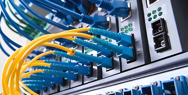
Specify inspection, cleaning, continuity, polarity, insertion loss, OTDR, return loss, end-face records and as-built documentation as required.
A Practical RFQ Checklist
Before requesting a fiber package for a wireless deployment, provide enough information to define endpoints, routes, interfaces, capacity and acceptance.
Network Architecture
- Deployment type: macro backhaul, small cell, indoor or outdoor DAS, fronthaul or midhaul
- A-end and Z-end of each passive link
- Point-to-point, ring, star, daisy-chain or branched topology
- Active-equipment interfaces and responsible equipment vendor
- Primary and protection paths
Route and Environment
- Route length by aerial, duct, direct-buried and indoor section
- Maximum aerial span, duct dimensions and pulling constraints
- Temperature, moisture, UV, wind, ice, rodent or chemical exposure
- Building flame/smoke classification and local code basis
- Entry points, handholes, poles, rooftops and cabinet locations
Optical and Mechanical Requirements
- Fiber type and total fiber count
- Fibers required at each drop point
- Spare-fiber and future-capacity policy
- Cable diameter limits and minimum bend radius
- Tensile, crush, impact and ingress-protection requirements
Termination and Testing
- Connector type and UPC/APC polish at both ends
- Splice versus pre-terminated installation
- ODF, terminal, closure and splice-tray capacity
- Required wavelengths and test directions
- Insertion-loss, OTDR and return-loss acceptance limits
- Labeling, test-file format and as-built documentation
Common Planning Mistakes
Treating DAS and Small Cells as the Same Architecture
Both can improve coverage and capacity, but their topology, ownership, equipment interfaces, power design and fiber distribution may be different. Build the BOM from the selected architecture.
Counting Only Active Fibers
A design based only on initial active links may omit maintenance spares, protection, additional operators or later radio expansion. Capacity planning should consider the full service life of the passive route.
Selecting Cable Before Mapping the Route
A route can cross several environments. Buying one cable construction before identifying aerial, underground, building-entry and indoor sections can create compliance or installation problems.
Ignoring Distributed Maintenance
More edge locations mean more labels, ports, connectors and potential fault points. Standardized closures, terminals, patching and documentation can reduce training, inventory and restoration time.
Assuming Fiber Solves Every Availability Problem
Fiber capacity does not compensate for a shared duct, unprotected hub, congested enclosure or undocumented splice plan. Physical route diversity and maintainable passive design matter as much as transmission capacity.
Conclusion: The Wireless Edge Is Becoming Fiber-Rich
5G densification does not replace fiber with radio. It changes where fiber must go and how many locations the passive network must support. Macro-site upgrades raise backhaul capacity requirements, small cells multiply endpoints, DAS distributes connectivity across buildings and venues, and disaggregated RAN adds defined fronthaul and midhaul interfaces.
For network buyers, the key shift is from purchasing isolated components to defining a repeatable site architecture. Start with endpoints, topology, route conditions, capacity, interfaces and acceptance criteria. Then align the cable, closure, terminal, ODF, patching and test plan around that design.
References
- Clearfield expands wireless infrastructure market reach through WAV, September 2, 2026.
- Clearfield: Simplifying Fiber Connectivity Across the Wireless Network.
- Corning: How 5G Networks Will Impact Fiber-Optic Cabling Requirements.
- Small Cell Forum: Call to Action on Densification, February 24, 2026.
- Ericsson: 5G Explained.
- ZION: Tower Fiberization BOM Checklist.
- MLS names Boldyn Networks the league’s official DAS partner, March 5, 2025.
- Boldyn brings permanent high-capacity 5G to Silverstone, February 17, 2025.
- Boldyn and Seattle-Tacoma International Airport announce a next-generation 5G DAS, January 13, 2026.
Frequently Asked Questions
Why does a wireless 5G network need fiber?
The wireless connection usually covers only the link between a device and a nearby radio. Fiber can carry aggregated traffic from radio sites through fronthaul, midhaul or backhaul networks to aggregation and core locations with high capacity, low attenuation and strong upgrade potential.
Do all 5G small cells require fiber backhaul?
No. Small cells may use fiber, Ethernet over another access medium, microwave or millimeter-wave backhaul depending on site conditions and operator design. Fiber is often selected for high-capacity or long-life deployments, but the correct choice depends on capacity, latency, route access, cost and resilience.
What is the difference between 5G backhaul and fronthaul?
Backhaul generally connects a cell site or RAN location toward an aggregation or core network. Fronthaul connects radio-related units near the antenna to baseband or distributed processing. Actual boundaries depend on the RAN architecture, so procurement documents should define the physical endpoints.
Does DAS use fiber optic cable?
Many DAS architectures use fiber between a central head-end or hub and remote units, followed by shorter connections toward antennas. The exact use of fiber, coaxial cable or hybrid cabling depends on the DAS design and equipment vendor.
How many fibers are needed for a 5G cell site?
There is no universal number. Fiber count depends on the active interfaces, duplex or bidirectional optics, number of sectors and bands, protection design, topology, spare-fiber policy and future expansion. The count should be calculated from the network architecture rather than assigned from a generic rule.
Prepare a Coordinated 5G Fiber Package
Share the route drawing, fiber allocation, cable environments, enclosure locations, connector interfaces, active-equipment details, quantities and acceptance requirements so ZION can support project-specific passive fiber planning for tower backhaul, DAS and small-cell routes.
Request Project Support



 Fiber Optic Cable
 Fiber Optic Tools
 Ethernet Cable
 Coaxial Cable
 Fire & Security Cable
 Voice, Audio & Video
 Power & Control Cable