Start with the Link, Not the Product List
Before selecting any hardware, define five project boundaries: network endpoints, route, topology, capacity and acceptance basis. These decisions control the cable construction, fiber count, closure layout, ODF density, patching interfaces and test workload.
Confirm where the passive link starts and ends: tower shelter, outdoor cabinet, aggregation node, handhole, central office or another tower. Then separate the route into aerial, duct, direct-buried, indoor and transition sections. A point-to-point spur, ring, daisy chain or mid-span branch will produce a different bill of materials even if the total route distance is similar.

Identify the near-end and far-end facilities, equipment rooms, cabinets and access points before assigning cable or ODF line items.
Record wavelengths, test directions, instruments, file formats and pass/fail limits required by the operator or project specification.
Tower Fiber Backhaul Reference Path
A typical passive path may be arranged as follows: aggregation network to feeder cable, branch splice closure, tower access cable, site ODF or termination box, patch cord and transmission equipment.
Not every project needs every element. A dedicated point-to-point route may not need a branch closure. A short cabinet-to-cabinet link may use a compact termination box instead of a full rack-mount ODF. A ring site may need two physically diverse cable entries and separate routing inside the cabinet. The correct BOM comes from the route drawing and splice plan, not from a generic tower kit.

1. Fiber Cable BOM
Select cable construction by installation environment. Aerial routes, ducts, direct-buried sections and building entries place different mechanical, environmental and regulatory demands on the cable package. ZION's optical fiber cable portfolio and ADSS cable selection guide are useful internal references when converting route inputs into a quotation request.
| Route section | Typical cable family | RFQ fields that must be confirmed |
|---|---|---|
| Aerial route between poles or support structures | ADSS or another project-approved self-supporting aerial cable | Maximum span, average span, sag criteria, wind and ice load, installation tension, cable attachment position, sheath requirement, hardware set and environmental conditions |
| Duct or subduct | Outdoor loose-tube duct cable; armored or all-dielectric construction according to route risk | Duct size, cable outside diameter, pulling length, allowable pulling tension, crush exposure, water blocking, rodent risk, drum length and pulling direction |
| Direct-buried route | Direct-burial outdoor cable with the mechanical protection required by the specification | Soil and moisture conditions, burial method, armor requirement, crush and impact risk, rodent protection, route markers and local civil-work rules |
| Building or shelter entry | Project-approved outdoor/indoor cable, or an outdoor-to-indoor transition using a splice enclosure | Entry distance, local fire code, indoor flame rating, pathway, bend radius, sealing and transition location |
| ODF to active equipment | Factory-terminated single-mode patch cord | Connector type at both ends, UPC or APC polish, fiber category, length, jacket rating, duplex/simplex format and equipment-vendor requirement |
IEC 60794-3-10 covers optical telecommunication cables for duct, direct-buried and lashed-aerial applications. IEC 60794-4-20 addresses construction, optical and mechanical performance, environmental considerations and accessory compatibility for ADSS cable. These standards are useful reference points, but the purchaser still needs a project-specific cable datasheet and acceptance criteria.
Confirm the fiber specification separately from the cable construction. Many tower backhaul projects use single-mode fiber. ITU-T G.652 defines the characteristics of a single-mode fiber and cable optimized around 1310 nm and usable in the 1550 nm region. ITU-T G.657 defines bending-loss-insensitive single-mode fiber categories with improved bend performance. Do not treat "single-mode", "OS2", "G.652.D" and "G.657.A2" as interchangeable shorthand.
Build fiber count from the architecture: working fibers plus protection fibers plus planned services plus maintenance reserve plus future expansion. Coordinate the selected count across cable fiber count, splice tray and closure capacity, ODF ports and pigtails, adapter and patch-cord count, test quantity and documentation schedule.
Cable line items normally included
- Main outdoor fiber-optic cable, by route section and drum length
- Indoor or outdoor/indoor transition cable, if required
- Factory-terminated fiber patch cords for equipment connection
- Cable glands, entry seals and protective conduit
- Aerial suspension or dead-end sets, downlead clamps and mounting hardware, where applicable
- Cable identification tags, warning tape or route markers
- Route-specific slack storage hardware
- Grounding and bonding materials for metallic cable elements, if present and required by the local design
2. Splice Closure BOM
The splice closure protects the optical joint and manages buffer tubes, bare fibers, splice sleeves and stored fiber. Closures may be installed aerially, on a pole, in a handhole or manhole, or in a direct-buried environment. For ZION-linked route planning, buyers can review passive optical components through the Optical Communication System solution and matched fiber-management accessories.

| Selection field | What to verify |
|---|---|
| Installation environment | Aerial, pole-mounted, handhole/manhole, direct buried, wall-mounted or cabinet |
| Topology | Butt, inline, branch, express/mid-span access or full cable cut |
| Total splice capacity | Day-one splices plus planned branch and expansion splices, not merely the core count of one cable |
| Tray arrangement | Splices per tray, number of trays, single-fiber or ribbon management, hinge/access direction |
| Cable ports | Number, type and usable cable-diameter range for every incoming and outgoing cable |
| Sealing method | Mechanical, gel, gasket or heat-shrink system; suitability for repeated re-entry |
| Environmental rating | Required ingress, impact, UV, temperature, chemical and submersion performance supported by requested test evidence |
| Cable retention | Strength-member anchoring, sheath retention and strain relief compatible with the cable construction |
| Documentation | Port map, tray map, fiber color code, sealing procedure and re-entry instructions |
A closure advertised as "96-core" may still be wrong if its ports do not accept the specified cable diameter, if it cannot support the branch topology, or if its sealing method is unsuitable for the location.
Closure line items normally included
- Complete dome or inline closure body
- Required splice trays and tray covers
- Fiber installation accessories, splice trays and heat-shrink splice protection sleeves
- Cable-entry seals or gland kits matched to actual cable diameters
- Strength-member clamps and cable-retention hardware
- Pole, wall, strand or handhole mounting kit
- Grounding or bonding kit where required
- Fiber labels, tray labels and external identification tag
3. ODF and Termination BOM
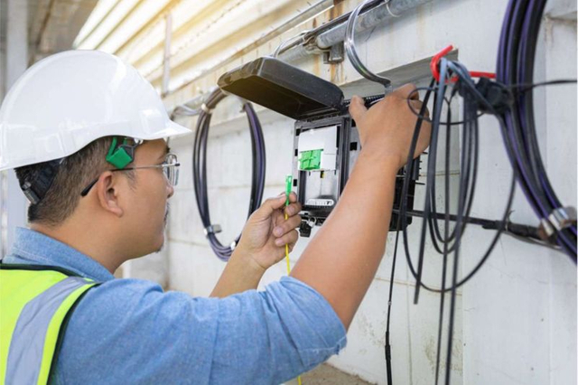
An optical distribution frame is the controlled interface between outside-plant fibers and patch cords serving active equipment. It provides termination, routing, protection and access for moves, adds and maintenance. ZION's optical communication solution includes termination and distribution products that can be coordinated with fiber cable, trays, adapters, pigtails and patch cords.
| Selection field | What to verify |
|---|---|
| Form factor | 19-inch rack-mount, wall-mount box, outdoor cabinet module or floor-standing frame |
| Port capacity | Day-one terminations plus approved spare capacity |
| Adapter interface | LC, SC or project-specific interface; simplex or duplex; UPC or APC polish |
| Termination method | Fusion-spliced pigtails, pre-terminated cassette, field-installable connector or another operator-approved method |
| Fiber management | Splice trays, bend-radius control, incoming-cable anchoring, slack storage and patch-cord routing |
| Access and security | Front/rear access, removable panels, lock, technician clearance and cabinet compatibility |
| Labeling | Site ID, cable ID, tray, port, fiber, far-end destination and service mapping |
| Environmental suitability | Indoor or outdoor cabinet location, temperature, dust, moisture and corrosion exposure |
ODF line items normally included
- ODF chassis or wall-mount termination box
- Adapter plates or modular panels
- Fiber adapters with the specified connector and polish
- Factory-terminated pigtails and patch cords matching the fiber and adapter interface
- Splice trays and splice sleeves
- Cable glands, strength-member clamps and entry hardware
- Patch cords matching both the ODF and transmission equipment
- Horizontal or vertical patch-cord managers where needed
- Blank plates, dust caps and spare port protection
- Port, cable and service labels
UPC and APC interfaces must not be mixed. Connector color alone should never be the acceptance method; verify the connector designation, adapter and equipment port schedule.
4. Installation Consumables and Field Tools
A complete passive BOM should also account for the items technicians need to build the link. Missing inspection tips, incompatible splice sleeves or the wrong cable-entry kit can stop commissioning even when the major products are already on site.
- Fusion splicer with the correct holders and electrodes
- Precision cleaver, fiber strippers and cable-sheath tools
- Cleaning fluid and lint-free wipes approved for optical work
- Connector cleaning tools for the specified interfaces
- Inspection probe and tips for every connector type in the project
- Fiber disposal container and basic safety equipment
- Buffer-tube routing tools, markers, labels and tie materials approved for fiber use
- Closure sealing tools and torque tools required by the manufacturer
- Cable pulling and aerial installation tools appropriate to the route
- Laptop or mobile device for splice records, OTDR files and as-built updates
ZION's fiber-optic tools category can support the tool and accessory portion of the procurement discussion when the project requires a coordinated field kit.
5. Test Equipment BOM
The test package should be defined in the contract before installation begins. Connector inspection, continuity checks, insertion-loss measurement, OTDR event review, ORL where required and live equipment power checks serve different purposes.

| Test item | Purpose | Typical equipment |
|---|---|---|
| Connector end-face inspection | Identify debris, scratches and defects before mating | Video inspection probe with correct adapter tips |
| Continuity and identification | Confirm fiber routing and find gross faults | Visual fault locator or fiber identifier used under the approved safety procedure |
| End-to-end insertion loss | Measure total installed-link loss in a way that represents transmitter-to-receiver operation | Calibrated optical loss test set, or light source and power meter with reference cords |
| Event location and splice review | Locate splices, connectors, macrobends, breaks and route distance | Single-mode OTDR with launch and receive fibers |
| Optical return loss | Verify ORL when required by the active system or operator | ORL-capable test set or approved method |
| Live equipment power | Confirm transmitted and received power after activation | Optical power meter with appropriate wavelength and power range |
IEC 61300-3-35:2022 covers visual inspection and classification of contamination and defects on fiber-optic connector end faces. It explicitly notes that visual inspection does not replace optical performance measurements. For installed single-mode cable plants, attenuation and return loss are covered by IEC 61280-4-2.
An OTDR is not a substitute for an insertion-loss measurement. The Fiber Optic Association testing reference explains that a source and power meter measure link loss directly, while an OTDR is used to characterize and locate events. Launch and receive cables are normally needed when both end connectors must be assessed.
6. Commissioning and Acceptance Checklist
The acceptance checklist should connect field construction to measurable proof. It also protects future maintenance by ensuring that trace files, port schedules and as-built drawings are delivered together.
Before testing
- Confirm the approved route drawing, splice plan, port schedule and equipment interface schedule.
- Record cable manufacturer, cable type, drum number, printed length marks and installed section.
- Verify that cable pulling tension, bend radius and aerial sag requirements were followed.
- Check closure mounting, sealing, strain relief, cable entry and tray routing.
- Check ODF anchoring, cable retention, bend-radius control, patch routing and labeling.
- Confirm bonding and grounding where metallic elements are present.
- Inspect, clean and re-inspect every connector before mating.
- Verify instrument calibration status, wavelength capability, reference cords and connector adapters.
Passive-link tests
- Confirm continuity and fiber identity from end to end.
- Measure insertion loss at the project-specified wavelength or wavelengths.
- Acquire OTDR traces using project-approved range, pulse width, index and averaging settings.
- Use launch and receive fibers when end-connector events must be included.
- Test from both directions when required; bidirectional averaging can reduce directional splice-measurement effects.
- Measure ORL if specified for the system.
- Compare measured results with the engineered loss budget and contractual limits.
- Investigate unexpected reflective events, high-loss splices, localized attenuation or route-length discrepancies.
After activation
- Confirm transmitter output and received optical power against the equipment vendor operating range and approved power budget.
- Check the intended service and protection paths.
- Save native instrument files as well as human-readable PDF or CSV reports if required.
- Update the as-built route, closure port map, splice tray map, ODF port map and equipment patch schedule.
- Record the final configuration as the maintenance baseline.
7. Sample Procurement BOM Template
The following structure supports quantity take-off. Quantities must be populated from the route survey, splice plan and port schedule.
| Item | Description | Quantity basis | Required submittal |
|---|---|---|---|
| 1 | Outdoor single-mode fiber cable | Surveyed route plus engineered slack and drum plan | Cable datasheet, fiber certificate, drum test report |
| 2 | ADSS hardware set, if aerial | Per support type, angle, dead-end and span design | Compatibility statement and installation drawing |
| 3 | Outdoor splice closure | Per joint or branch location and topology | Datasheet, port/cable-diameter table, tray layout, environmental test evidence |
| 4 | Splice trays | Total planned splices plus approved expansion | Tray capacity and routing drawing |
| 5 | Splice protection sleeves | One per fusion splice plus project spare | Size compatibility |
| 6 | ODF or termination box | Per site and required port capacity | Mechanical drawing, port layout, material list |
| 7 | Adapters | Per terminated port plus approved spare | Connector and polish specification |
| 8 | Pigtails | Per fusion-terminated port plus approved spare | Fiber category, connector, polish, length and test data |
| 9 | Patch cords | Per working/protection interface plus approved spare | End-A/End-B connector, polish, fiber, jacket and length |
| 10 | Cable glands and entry kits | Per cable entry and actual cable diameter | Diameter range and sealing method |
| 11 | Mounting and slack-storage hardware | Per site construction drawing | Material and load/environment suitability |
| 12 | Labels and identification | Per cable, closure, tray, fiber and ODF port | Label schedule and durability requirement |
| 13 | Cleaning and inspection kit | Per field team | Connector-tip list and cleaning method |
| 14 | OLTS/source and power meter set | Per commissioning team | Calibration record and wavelength range |
| 15 | OTDR with launch and receive fibers | Per commissioning team | Calibration record, wavelength range and native file format |
| 16 | Handover documentation | Per link/site | As-built drawing, splice map, port schedule, test files and exceptions list |
8. RFQ Checklist for ZION
To receive a technically matched cable, closure and ODF proposal, include the following information in the RFQ. With these inputs, ZION can align fiber cable, splice closure, ODF, pigtails, patch cords and installation accessories as one coordinated passive package instead of a set of disconnected part numbers.
Country, installation location, site count, topology, route length by section, aerial span, pole/tower/shelter/cabinet details, drum lengths and delivery schedule.
Fiber category and count, working/protection plan, operating wavelengths, active-equipment interface, connector type, UPC/APC polish and engineered link-loss budget.
Number and outside diameter of every entering cable, butt/inline/branch/mid-span topology, required splice capacity, tray arrangement, ODF form factor and port schedule.
Applicable standards, factory tests, certificates, field-test method, wavelength, direction, acceptance limits, report format, labeling, packing and as-built requirements.
9. Common BOM Mistakes
Buying cable by core count alone
Fiber count does not define aerial span capability, crush resistance, cable diameter, sheath or installation hardware.
Matching closure capacity only to one cable
A branch closure may hold splices from several cables, express fibers and future trays. Calculate the full splice plan.
Ignoring actual cable diameter at the closure
The correct number of ports is useless if the sealing kits do not fit the installed cables.
Mixing UPC and APC interfaces
Polish type must be consistent with adapters, pigtails, patch cords and active-equipment ports.
Ordering an OTDR without launch and receive fibers
This can prevent proper characterization of the first and last connectors.
Treating OTDR loss as the end-to-end acceptance result
Use the specified insertion-loss method for total link loss and the OTDR for event characterization, unless the operator written procedure states otherwise.
Forgetting native test files and as-built records
A link may pass on installation day but remain difficult to maintain if its traces, splice map and port schedule are missing.
FAQ
What cable is normally used for tower fiber backhaul?
It depends on the route. ADSS is a common option for self-supporting aerial sections; outdoor loose-tube cable is commonly considered for duct routes; direct-burial cable is selected where the cable is placed in the ground. The project specification must define mechanical, environmental and optical requirements.
How many fibers should a tower backhaul cable have?
Calculate the count from active services, duplex or bidirectional optics, protection architecture, planned services, maintenance reserve and expansion. There is no universal core count for every tower.
Does every tower site need a splice closure?
No. A closure is needed where fibers are spliced, branched, accessed mid-span or transitioned. A dedicated unspliced cable may terminate directly in the site ODF, subject to the route and building-entry design.
Should an ODF use LC or SC connectors?
Use the interface required by the operator and active equipment. Confirm connector format and UPC/APC polish at both ends before ordering adapters, pigtails and patch cords.
Are OTDR tests enough for tower fiber acceptance?
Not usually. OTDR testing characterizes events and distance, while an OLTS or source-and-power-meter test measures end-to-end insertion loss. The final test set must follow the operator acceptance specification.
Conclusion
A reliable tower fiber backhaul BOM connects four disciplines: route engineering, passive product selection, installation practice and measurable acceptance. Cable, closure and ODF choices must share the same fiber count, cable dimensions, connector interface, topology and expansion plan. The test checklist must then prove that the installed system matches the design.
For a project-specific ZION BOM, provide the route type and length, maximum aerial span, fiber count, cable diameters, splice topology, ODF interface, active-equipment connectors and acceptance standard. That information is the shortest path from a generic inquiry to a buildable tower fiberization package.



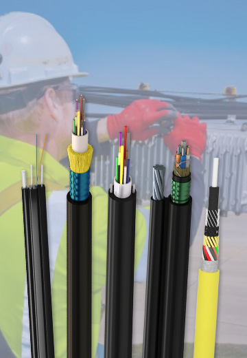 Fiber Optic Cable
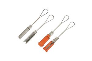 Fiber Optic Tools
 Ethernet Cable
 Coaxial Cable
 Fire & Security Cable
 Voice, Audio & Video
 Power & Control Cable