Type designation of RF coaxial connector
Author: Elsie Publish Time: 29-07-2019 Origin: Site
RF Coaxial Connector Type Designations: How to Read Product Codes Decode RF connector family names, impedance, housing style, center contact, mounting method and cable termination without assuming that one manufacturer's suffixes apply to every supplier. |
An RF coaxial connector part number can contain useful information about the interface family, plug or jack body, center contact, mounting geometry, termination method and compatible cable. However, these elements are not encoded in one universal industry-wide format. Names such as SMA, TNC, MCX and Type N identify recognized connector families, while the letters and numbers that follow are normally defined by the manufacturer.
Use the code as a fast screening tool, then confirm the mechanical drawing and datasheet before ordering. The equipment interface, center-contact configuration, characteristic impedance, cable construction, mounting method and frequency requirement must all agree.
■What a Connector Code Can and Cannot Tell You
The first part of a designation usually identifies the connector family, for example TNC, MCX, SSMB, SMA, RP-SMA or N. A suffix may then describe features such as straight or right-angle construction, plug or jack housing, pin or socket center contact, flange or bulkhead mounting, cable size, crimp termination or PCB mounting.
| Important: The suffix meanings in this guide explain the coding system used by the examples on this ZION page. Do not assume that another manufacturer uses the same letters. Always verify the product drawing, interface description and cable compatibility. |
■Connector Family Names Come First
Connector family names define the mating interface more reliably than a supplier-specific suffix. Interface standards establish items such as mating dimensions, coupling method and characteristic impedance for a connector series. They do not create one universal commercial part-number format for every cable attachment, body style and mounting option.
| Family | Typical coupling | What still needs confirmation |
| SMA / RP-SMA | Threaded | Standard or reverse-polarity interface, center contact, impedance, frequency range and mounting form |
| TNC | Threaded | 50 or 75 ohm version, body gender, contact gender, cable attachment and environmental rating |
| MCX | Push-on / snap-on | Straight or right-angle body, cable size, center contact, termination and board or cable mounting |
| SSMB | Snap-on | Interface variant, PCB or cable termination, center contact and detailed manufacturer dimensions |
| Type N | Threaded | 50 or 75 ohm interface, contact configuration, sealing, cable size and attachment method |
■How to Read the Structural Codes
The examples on this page combine a connector-family name with structural characters. A hyphen normally separates the family from the structural description. Some positions may be omitted when a feature is considered the default, and a final number may identify a cable size or an internal product sequence.
| Code element | Meaning in this page's system | Selection note |
| T / Z | Plug or jack/socket body designation | Confirm the mating shell and coupling mechanism; do not infer the center contact from the housing alone. |
| 50 / 75 | Characteristic impedance when explicitly stated | Impedance must match the connector interface, coaxial cable and system. An omitted value is not proof of 50 ohms. |
| J / K | Pin or socket center contact | Reverse-polarity families intentionally separate housing style from center-contact gender. Verify both. |
| W | Right-angle body; straight may be unmarked | Choose by equipment clearance, cable exit direction, minimum bend radius and service access. |
| F / Y | Flange or nut/bulkhead mounting | Confirm panel thickness, mounting-hole dimensions, anti-rotation features and sealing needs. |
| C / B / D / E | Crimp, semi-rigid/semi-flex, microstrip or PCB termination | Use the assembly instruction for the exact part. Similar-looking connectors may require different strip lengths, ferrules and tooling. |
| Cable-size number | Nominal cable or dielectric size in the supplier's system | Match the exact cable construction, not only a generic RG or metric family name. |
■Worked RF Connector Examples
TNC-J3
In this coding system, TNC-J3 identifies a straight TNC cable plug with a pin center contact for the indicated cable-size group. It is associated with SYV-50-3 or RG58/U-type cable and a clamp-style termination. Before substitution, confirm the exact cable dimensions and assembly instruction.

MCX-C-JW1.5
MCX-C-JW1.5 describes an MCX right-angle cable plug with a pin center contact and crimp termination for a small flexible coaxial cable group. It is associated with SFF-50-1.5-1 or RG174/U-type cable. The ferrule, center contact and strip dimensions must match the actual cable.

SSMB-TKE-6
SSMB-TKE-6 identifies a straight SSMB PCB-mount plug body with a socket center contact and 50-ohm interface. The final “-6” is the company's product sequence number rather than an industry performance class.

RP-SMA-C-ZJY1.5
This example identifies a reverse-polarity SMA bulkhead cable connector with a pin center contact, nut mounting and crimp termination for the stated cable-size group. Reverse polarity changes the center contact associated with the plug or jack housing, so the drawing and mating interface must be checked directly.

■Adapter and Impedance Converter Codes
SMA-50JK
This is presented as a 50-ohm SMA in-series adapter with a pin contact at one end and a socket contact at the other. An adapter description should also confirm the housing configuration on both ends because contact gender alone does not fully define the mating interface.

N-50J/75K
This designation describes an N-type impedance-matching adapter with a 50-ohm pin-contact side and a 75-ohm socket-contact side. A true impedance converter should not be treated as a simple mechanical gender adapter; verify its electrical specification, operating frequency and return-loss data for the intended system.

■Plug, Jack, Pin and Socket Are Different Details
RF connector descriptions often combine two separate ideas: the mechanical housing that mates and locks the connector, and the electrical center contact that carries the RF signal. In a conventional SMA interface, a plug housing normally has a pin center contact and a jack housing normally has a socket contact. RP-SMA intentionally reverses the center contacts while retaining the corresponding outer interface.
| Description layer | Terms | What to inspect |
| Outer housing | Plug, jack, receptacle | Threads, bayonet or snap-on mechanism, external or internal coupling surfaces and panel geometry |
| Center contact | Pin, socket, male, female | Whether the center conductor projects as a pin or accepts the mating pin as a socket |
| Polarity system | Standard or reverse polarity | The complete mating interface; standard and reverse-polarity parts are intentionally non-mating |
■RF Connector Selection Checklist
Interface family: Identify the exact SMA, RP-SMA, TNC, MCX, SSMB, N-type or other mating interface.
Characteristic impedance: Confirm 50 or 75 ohms across the connector, cable and equipment port.
Housing and center contact: State both plug/jack body and pin/socket center contact, especially for reverse-polarity connectors.
Frequency and power: Use the exact product datasheet rather than a typical family value.
Cable compatibility: Confirm conductor diameter, dielectric diameter, shield construction, jacket diameter and cable flexibility.
Termination method: Specify crimp, clamp, solder, semi-rigid, microstrip or PCB termination and the required tooling.
Mounting and geometry: Confirm straight or right-angle exit, flange or bulkhead mounting, panel thickness and available clearance.
Environmental requirements: Check sealing, temperature, vibration, corrosion and outdoor exposure where applicable.
For feeder-cable projects, ZION's connectors for D-FB coaxial cable illustrate why the exact cable size, equipment interface and straight or right-angle routing requirement should be submitted together.
■Frequently Asked Questions
Are RF connector suffix codes universal?
No. Connector-family names and standardized mating interfaces are broadly recognized, but commercial suffixes and part-number positions are manufacturer-specific. Use the supplier's datasheet and drawing.
Does “plug” always mean a pin center contact?
No. A conventional interface often pairs a plug housing with a pin contact, but reverse-polarity designs intentionally change that relationship. Describe the housing and center contact separately.
Can I select an RF connector using only the cable name?
No. Cable names can cover different constructions. Confirm the actual conductor, dielectric, shield and jacket dimensions plus the connector manufacturer's supported cable range.
What information should be included in an RF connector inquiry?
Provide the connector family, standard or reverse polarity, plug or jack housing, pin or socket contact, impedance, exact cable model, straight or right-angle body, mounting method, termination method, frequency range, environment and quantity.



 Fiber Optic Tools
Products 6 families
Solutions 6 markets
Resources Tools & docs
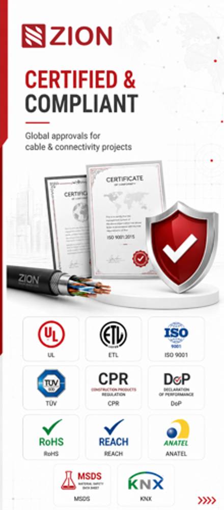
Certificate
Certification and compliance references for project review, qualification and purchasing documentation.
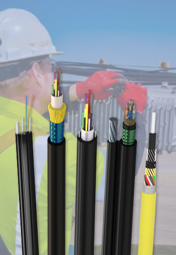 Fiber Optic CableAccess and backbone
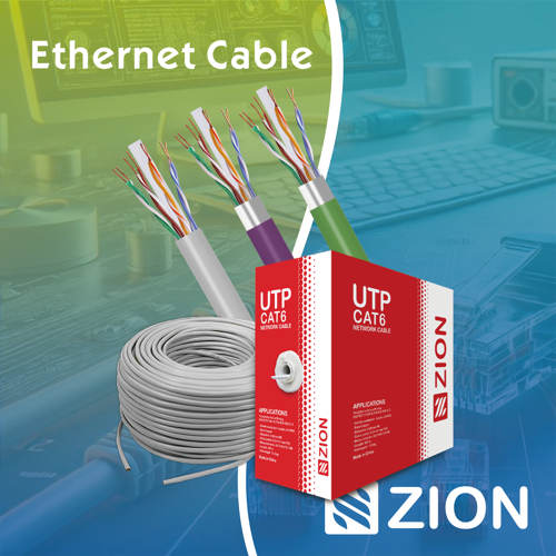 Ethernet CableCat5e to Cat8
 Coaxial CableRF and video signal
 Fire, Security & AlarmSafety systems
 Voice, Audio & VideoSignal cabling
 Power & Control CableEnergy and control
Fiber optic cable systems
Outdoor, indoor, FTTH and distribution cable lines for access networks, backbone routes and campus deployments.
 Telecom & ISP NetworksFTTH, PON, ODN
 Data Center InfrastructureServer room cabling
 Building Low-Voltage SystemsBMS, AV, weak current
 Security & Fire ProtectionAlarm, CCTV, access
 Industrial Automation CablePLC, RS485, fieldbus
 Energy & Power InfrastructureSolar, battery, power
Telecom & ISP Networks
For FTTH / PON access, outdoor fiber deployment, aerial routes, duct routes, direct burial routes, rural broadband and ODN planning.
Tools
Use calculators and planning tools for conduit capacity, PoE voltage drop and fiber optic link loss budget work.