5 Steps of Network Cable Manufacturing
Author: Site Editor Publish Time: 19-04-2021 Origin: Site
How Network Cable Is Manufactured
Five controlled stages turn copper conductor and polymer compounds into finished twisted-pair cable: conductor preparation, insulation, pair formation, cable assembly and jacketing, followed by final verification and packing.
Network cable manufacturing is a sequence of tightly controlled mechanical and electrical processes. The exact materials, dimensions, shielding and test limits depend on the cable category, application, jacket rating and product specification. Cat5e, Cat6, Cat6A and higher-performance constructions therefore do not all use the same tooling or process settings, even though their main production stages are similar.
Process overview: Copper is drawn and annealed, insulation is extruded around each conductor, insulated conductors are twisted into balanced pairs, the pairs are assembled with any required separator or shield, and the finished core receives its jacket, markings, tests and final packaging.
■Step 1: Copper wire drawing and annealing
Production begins with copper rod or an intermediate conductor feedstock. A drawing machine pulls the copper through a sequence of progressively smaller dies until it reaches the diameter required by the approved cable construction. Lubrication reduces friction, removes heat and protects the die surface while line tension and conductor diameter are monitored.

Cold drawing work-hardens copper. Controlled annealing restores the ductility and elongation needed for later handling and termination. The annealing method, atmosphere, temperature profile and line speed are process parameters established for the conductor design; they should not be treated as one universal setting for every LAN cable.

What is checked at this stage?
Conductor diameter, roundness and surface condition
DC resistance against the product requirement
Elongation and tensile behavior after annealing
Spool identification and material traceability
■Step 2: Insulation extrusion and inline inspection
Each conductor passes through an extrusion crosshead, where a controlled layer of insulating polymer is applied. Material selection depends on the cable design and may include solid or foamed polyethylene-based compounds, fluoropolymer or another specified insulation system. Color control identifies the conductors that will form the four pairs.

The insulation must be concentric and consistent because its geometry affects capacitance, impedance and pair balance. After extrusion, the insulated conductor is cooled and measured. Inline systems can monitor outer diameter and eccentricity, while electrical or spark testing may be used to identify insulation faults according to the production plan.

Critical controls during insulation
Operators control compound condition, conductor preheat where required, extrusion temperature, line speed, cooling and take-up tension. Diameter, wall thickness, eccentricity, color and electrical integrity are checked before the insulated conductors move to pair twisting.
■Step 3: Pair twisting and cable core assembly
Two insulated conductors are twisted together to form a balanced pair. In a four-pair cable, the pairs normally use different lay lengths to manage coupling between adjacent pairs. Twist control, conductor spacing and tension all influence characteristic impedance, return loss, insertion loss and crosstalk performance.

The four completed pairs are then laid together into the cable core. Depending on the construction, the core may include a cross separator, filler, ripcord, drain wire, pair foil or overall shield. These components are design-specific: an unshielded Cat5e cable, a separator-based Cat6 cable and a shielded Cat6A cable do not have identical cores.
Why twisting matters: balanced transmission allows the receiver to respond to the voltage difference between conductors while rejecting much of the noise coupled similarly onto both conductors. Pair geometry must still be controlled carefully; twisting alone does not guarantee category performance.
■Step 4: Shielding, water blocking and jacket extrusion
The assembled core receives only the protective components required by its approved construction. A shielded network cable may use foil around the core, foil around individual pairs, braid, a drain wire or a combination of these. Outdoor or direct-burial products may add water-blocking materials, a PE jacket, armor or multiple jackets. Indoor products may use PVC, low-smoke halogen-free or plenum-rated jacket compounds as specified.

The jacket compound is extruded around the cable core, cooled, dried and measured. Printing or embossing identifies information required by the product and market, such as the manufacturer, cable type, category, jacket or fire rating, length marking and traceability code. The exact marking content depends on the product specification and applicable certification program.
Not every cable receives gel, armor or a metal shield
These are optional construction elements selected for a defined environment or electrical requirement. Armor provides mechanical protection but does not by itself prove rodent resistance, lightning protection or direct-burial suitability. Shielding also requires compatible connectivity and a deliberate bonding and grounding design in the installed system.
■Step 5: Finished-cable testing, marking and packing
Quality control is not limited to one final test. Incoming material checks and in-process measurements are combined with finished-cable verification. The release plan should match the cable category, construction, customer specification and certification requirements rather than applying one generic test list to every product.

Typical finished-cable checks
Conductor continuity, resistance and resistance unbalance
Characteristic impedance, insertion loss and return loss
Near-end crosstalk and other category-specific transmission parameters
Capacitance, delay and balance parameters where required
Outer diameter, jacket thickness, surface quality and marking
Length, winding, packaging, label and traceability information
Accepted cable is wound into the specified coil, pull box, reel or drum. Packaging should protect the cable during transport and installation while preserving the requested length, payout direction, labels and batch identity.
■How manufacturing choices affect cable performance
The finished cable's performance comes from the complete construction. Copper diameter and conductivity influence resistance and PoE voltage drop. Insulation geometry affects impedance and capacitance. Pair lay and core assembly influence crosstalk and return loss. Shielding changes electromagnetic behavior and installation requirements, while the jacket determines where the cable may be installed.
The ZION factory and workshop page shows production areas for conductor preparation, insulation, pair twisting and cable forming. Buyers comparing finished constructions can also review the current ZION Cat6 Ethernet cable range to see how shielding, jackets and application ratings create different products within one category.
■What buyers should specify before production
A complete request for quotation helps the factory select the correct design and inspection plan. Provide the cable category, shielding construction, conductor type and size, jacket material and rating, application environment, PoE requirement, packing length, printing, color, certification market and required test documents.
Procurement check: Do not approve a cable from category name alone. Confirm the datasheet, conductor, shielding notation, jacket and fire rating, environmental suitability, dimensional drawing, packaging, cable marking and applicable test evidence.
■Frequently asked questions
What are the five main steps in network cable manufacturing?
They are conductor drawing and annealing, insulation extrusion, pair twisting and core assembly, shielding or jacketing as required, and finished-cable testing and packing.
Why do the four Ethernet pairs use different twist lengths?
Different pair lay lengths help manage electromagnetic coupling between adjacent pairs. The complete geometry and process control determine whether the cable meets its required crosstalk and impedance limits.
Is every network cable manufactured with shielding?
No. U/UTP cable has no overall or pair shield, while F/UTP, U/FTP, S/FTP and other designs use different shield arrangements. The correct structure depends on the category, electromagnetic environment, connectivity and grounding plan.
Which tests confirm Ethernet cable performance?
Testing commonly covers conductor resistance, balance, impedance, insertion loss, return loss and crosstalk, together with dimensional and construction checks. The required limits and sampling plan must match the claimed category and applicable product specification.



 Fiber Optic Tools
Products 6 families
Solutions 6 markets
Resources Tools & docs
Certificate
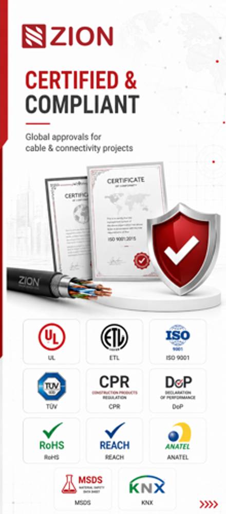
Certification and compliance references for project review, qualification and purchasing documentation.
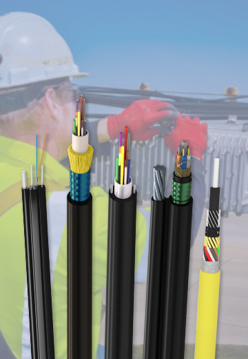 Fiber Optic CableAccess and backbone
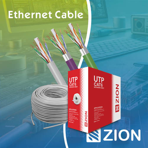 Ethernet CableCat5e to Cat8
 Coaxial CableRF and video signal
 Fire, Security & AlarmSafety systems
 Voice, Audio & VideoSignal cabling
 Power & Control CableEnergy and control
Fiber optic cable systems
Outdoor, indoor, FTTH and distribution cable lines for access networks, backbone routes and campus deployments.
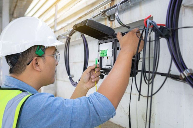 Telecom & ISP NetworksFTTH, PON, ODN
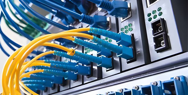 Data Center InfrastructureServer room cabling
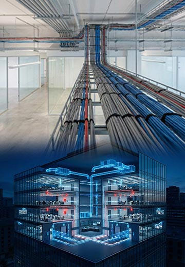
 Building Low-Voltage SystemsBMS, AV, weak current
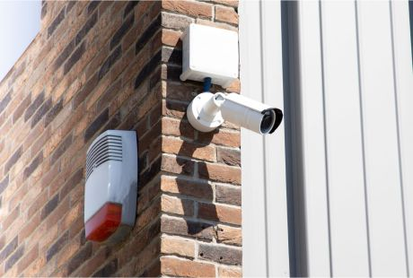 Security & Fire ProtectionAlarm, CCTV, access
 Industrial Automation CablePLC, RS485, fieldbus
 Energy & Power InfrastructureSolar, battery, power
Telecom & ISP Networks
For FTTH / PON access, outdoor fiber deployment, aerial routes, duct routes, direct burial routes, rural broadband and ODN planning.
Tools
Use calculators and planning tools for conduit capacity, PoE voltage drop and fiber optic link loss budget work.