- What Is a Data Center Cross Connect?
- Why OS2 Fiber Is Commonly Specified
- The Minimum Specification Should Not Be "OS2 LC-LC"
- Recommended OS2 Fiber Cross-Connect Specification Table
- Connector Choice: LC, SC, or MPO/MTP?
- UPC vs APC: Do Not Treat Polish as a Small Detail
- Loss Budget: Specify the Link Before You Install It
- Route Diversity Must Be Written Into the Request
- Testing, Labeling, and Handover
Carrier-neutral facilities depend on predictable physical interconnection. For a data center ICT contractor, an OS2 fiber cross-connect specification should be detailed enough for procurement, installation, testing, operations, and later capacity expansion.
Contents
What Is a Data Center Cross Connect?
A cross-connect is a dedicated physical cabling link between two parties or two network endpoints inside a data center facility. In carrier-neutral data centers, cross-connects often connect a customer cabinet to a carrier, cloud on-ramp, internet exchange, managed service provider, meet-me room, or another tenant environment.

Equinix documentation describes cross-connects as physical interconnection links inside its data centers for direct exchange between parties. The same operational principle applies across many carrier-neutral facilities: the cross-connect creates a controlled point-to-point physical path that avoids the unpredictability of routing everything across the public internet.
In practical projects, a fiber cross-connect may run from a customer cabinet to a meet-me room, from a carrier demarcation panel to an enterprise patch panel, between two cabinets in the same data hall, between a data hall and a network room, or between an optical distribution frame and active equipment.
Why OS2 Fiber Is Commonly Specified for Cross-Connects
OS2 is a single-mode optical fiber category used for long-distance and high-bandwidth transmission. In modern data centers, OS2 is commonly selected when the link must support 10G, 25G, 40G, 100G, 400G, and migration-ready optical paths, depending on the transceivers, channel design, and facility requirements.
OS2 fiber is especially useful for carrier-neutral data center cross-connects because it supports longer reach than many multimode use cases, lower attenuation over distance, carrier and cloud interconnection requirements, compatibility with many single-mode transceiver ecosystems, and future capacity upgrades without replacing the passive cabling path.
Carrier-neutral fit
OS2 single-mode fiber aligns well with carrier, cloud, internet exchange, and long-reach data center interconnection designs.
Migration headroom
A well-specified passive OS2 path can support later optical upgrades when the active equipment and link budget allow it.
Panel ecosystem
LC duplex patching, MPO/MTP trunks, ODF systems, and high-density panels are all common around OS2 cross-connect zones.
Contractor clarity
Clear OS2 requirements reduce ambiguity across procurement, cable preparation, installation, certification, and handover.
When specifying OS2 fiber, contractors should confirm whether the project requires ITU-T G.652.D, bend-insensitive G.657.A1/A2, or another single-mode fiber variant. ITU-T recommendations such as G.652 and G.657 are widely referenced when defining single-mode fiber characteristics.
The Minimum Specification Should Not Be "OS2 LC-LC"
Many project documents describe the requirement too briefly, for example: "Provide OS2 LC-LC fiber cross-connect between customer cabinet and MMR." That instruction may identify the rough cable family, but it does not provide enough information for a carrier-neutral data center environment.
A better specification should define fiber category and standard reference, connector type and polish, fiber count, duplex or multi-fiber format, cable construction, jacket rating, path type, route diversity requirement, maximum insertion loss, return loss expectation, polarity method, labeling convention, inspection and cleaning method, test method, reporting format, and handover documentation.
The more clearly these details are specified, the easier it is for the ICT contractor, data center operations team, and end customer to approve the installation. Vague wording can still produce a cable that looks correct, but later fails during commissioning, migration, or troubleshooting.
Recommended OS2 Fiber Cross-Connect Specification Table
The following table turns the common cross-connect discussion into a usable buyer and contractor checklist. It is not a substitute for the facility rule book, but it helps prevent missing fields in the RFQ, bill of materials, or installation method statement.
| Specification item | Recommended requirement | Notes for contractor or buyer |
|---|---|---|
| Fiber type | OS2 single-mode fiber | Confirm whether G.652.D or bend-insensitive G.657.A1/A2 is required. |
| Connector interface | LC duplex is common; MPO/MTP for high-density trunks | LC connector interface dimensions are standardized under IEC 61754-20. |
| Connector polish | UPC or APC, project-dependent | Do not mix UPC and APC on the same mated connection. |
| Fiber count | 2F, 4F, 8F, 12F, 24F, or project-specific | Match the current link, spare strategy, and future expansion requirement. |
| Cable construction | Duplex patch cord, breakout cable, trunk cable, or pre-terminated assembly | Select based on pathway, density, installation method, and bend control. |
| Jacket rating | LSZH, OFNR, OFNP, CPR, or local code requirement | Confirm with facility rules and local fire regulations. |
| Route | Standard, diverse, or physically separated path | For redundancy, specify diverse routing explicitly. |
| Polarity | A-to-B duplex or defined MPO/MTP method | Include the polarity map in the handover package. |
| Insertion loss | Define maximum link loss | Include connector, splice, adapter, module, fiber attenuation, and margin allowances. |
| Testing | OLTS plus inspection; OTDR when required | Record wavelength, direction, equipment model, and calibration status. |
| Labeling | Unique A-end and Z-end labels | Labels should match the order ID, cabinet, panel, port, and circuit ID. |
| Handover | Test reports, as-built route, photos, labels, and port map | Required for operations, audit trail, and future troubleshooting. |
Connector Choice: LC, SC, or MPO/MTP?
For many carrier-neutral data center cross-connects, LC duplex is the default connector format because it is compact, familiar, and compatible with a wide range of optical transceivers and patch panels. The LC interface is standardized in IEC 61754-20, which supports repeatability across multi-vendor environments.

SC may still appear in some carrier demarcation environments or legacy optical distribution frames. MPO/MTP is often selected for high-density trunks, structured cabling backbones, cassette systems, and breakout architectures where multiple fibers are routed through a compact pre-terminated assembly.
For ZION project positioning, the scope can include LC duplex OS2 patch cords for cabinet-to-panel and panel-to-equipment links, MPO/MTP trunk cables for structured cross-connect zones, MPO/MTP-to-LC high-density cabling for migration paths, and patch panel and cable management solutions for carrier-neutral meet-me room organization.
UPC vs APC: Do Not Treat Polish as a Small Detail
Connector polish affects optical return loss and physical compatibility. UPC connectors are commonly blue, while APC connectors are commonly green and use an angled physical contact surface. The two should not be mated together because a UPC/APC mismatch can cause high loss and connector damage.
Before ordering an OS2 fiber cross-connect, the contractor should confirm whether the carrier demarcation uses UPC or APC, whether the customer patch panel uses the same polish type, whether adapter panels are color-coded correctly, whether spare patch cords use the same polish, and whether test equipment is configured with the correct interface.
Practical check: polish type should be confirmed before cable preparation, labeling, and testing. It is one of the easiest details to catch early and one of the most frustrating problems to correct after a scheduled data center work window.
Loss Budget: Specify the Link Before You Install It
A fiber cross-connect may be physically short, but the optical loss budget still matters. A complete specification should define the maximum allowed insertion loss for the installed link, not only the cable type and connector interface.
A simple planning formula is:
Total link loss = fiber attenuation + connector pair loss + splice loss + adapter/module allowance + design margin
For example:
Fiber length: 100 m OS2
Fiber attenuation allowance: 0.4 dB/km at 1310 nm
Fiber loss: 0.04 dB
Connector pairs: 4 pairs × 0.3 dB = 1.2 dB
Design margin: 0.5 dB
Estimated total: 1.74 dB
The actual value should be adjusted based on project standards, transceiver limits, connector grade, panel architecture, and acceptance rules. For field certification, OLTS testing is commonly used to measure loss, while OTDR testing may be required to locate events or validate longer paths depending on the project requirement.
Route Diversity Must Be Written Into the Cross-Connect Request
Carrier-neutral data centers often provide different interconnection products or route options. If the customer requires resilience, the cross-connect request must clearly define whether the secondary path must be physically diverse from the primary path.

For an ICT contractor, route diversity should be specified with primary and secondary path identifiers, A-end and Z-end locations, cabinet, rack, panel, and port information, separation requirements, and whether diversity applies inside the data hall, riser, meet-me room, campus, or metro path.
If route diversity is only discussed verbally, it may not appear in the actual installation record. The acceptance package should show both paths separately, especially where redundant services, financial networks, cloud connectivity, or migration windows depend on physical separation.
Cable Construction and Bend Control
OS2 fiber cross-connects may use different cable constructions depending on the route. Common choices include duplex OS2 patch cords for short cabinet or panel patching, armored fiber patch cords where extra protection is required, breakout cables for multiple direct terminations, pre-terminated trunk cables for faster deployment, MPO/MTP patch panels and cassettes for high-density backbone connections, and ODF jumpers for meet-me room fiber management.
For dense data center environments, bend control is critical. Tight bends can increase insertion loss, especially when cables are routed through crowded trays, vertical managers, or high-density panels. Contractors should specify the minimum bend radius, cable management method, slack storage area, and patch cord routing discipline.
Inspection and Cleaning: Required Before Testing
Fiber connector contamination is one of the most common causes of optical link failure. Even a new patch cord should be inspected before mating. IEC 61300-3-35 defines inspection criteria for fiber optic connector end faces, including contamination and defects.
A practical contractor workflow is:
- Inspect the connector end face.
- Clean if contamination is found.
- Re-inspect after cleaning.
- Mate only clean connectors.
- Test the completed link.
- Save the inspection and test records.
This process is especially important in carrier-neutral facilities, where multiple contractors, carriers, and tenants may interact with shared patching zones.
Testing, Labeling, and Handover Requirements
The cross-connect should not be accepted based only on visual completion. A professional handover package should include insertion loss test results, test wavelength, test direction, OTDR trace if required, connector inspection record where required, equipment model and calibration status, A-end and Z-end port information, label photos, and an as-built route or panel map.
Labeling should be consistent at both ends and should match the customer order, data center record, and test report. Useful label fields include circuit ID or cross-connect order ID, A-end cabinet, panel, and port, Z-end cabinet, panel, and port, fiber count, connector type and polish, route type, installation date, and contractor or project reference.
Acceptance criteria should be agreed before installation. If the project only defines "test pass" without a numeric limit or method, disputes can occur during commissioning.
Common Mistakes When Specifying OS2 Cross-Connects
A short checklist can prevent most field problems. Avoid writing "OS2 LC-LC" without defining UPC or APC, forgetting to define maximum insertion loss, assuming duplex polarity without documenting A-to-B mapping, mixing different connector polish types, ordering the wrong fiber count for future growth, using a jacket rating that does not match facility rules, leaving route diversity out of the written request, testing without cleaning and inspection, or accepting handover without port maps and test reports.
These issues are usually inexpensive to prevent but expensive to fix after the data center window has closed.
Sample RFQ Text for an OS2 Fiber Cross-Connect
The following sample can be adapted for procurement or project documentation:
Provide OS2 single-mode fiber cross-connect cabling between A-end and Z-end locations within the carrier-neutral data center. Fiber shall be OS2 single-mode, connectorized as LC duplex UPC unless otherwise specified. Cable jacket rating shall comply with facility and local fire-code requirements. Contractor shall confirm A-end and Z-end port details, connector polish, route requirements, polarity, and maximum insertion loss before installation.

Installed link shall be inspected, cleaned, tested, labeled, and documented. Handover package shall include insertion loss test results, connector inspection record where required, port map, label photos, route information, and as-built documentation. If diverse routing is required, primary and diverse paths shall be documented separately.
How ZION Supports Data Center ICT Contractors
ZION can support ICT contractors, system integrators, telecom operators, and data center teams with fiber connectivity products used in cross-connect and structured cabling environments. Relevant solution areas include fiber patch cables, LC, SC, and MPO/MTP connectivity, pre-terminated fiber trunk assemblies, fiber patch panels and cable management, high-density fiber management solutions, data center fiber cabling accessories, custom length and connector configurations, and project-based support for fiber deployment.
Data Center Infrastructure
For cabinet, cabling, patching, and server room infrastructure planning.
LC-to-LC Fiber Patch Cord
For duplex LC patching between panels, racks, and active equipment.
MPO Trunk Cables
For pre-terminated high-density fiber backbone and cross-connect zones.
MPO Patch Panels and Cassettes
For organized fiber distribution, breakout, and migration-ready layouts.
For carrier-neutral data centers, the most valuable supplier is not simply the one that ships cable. It is the one that understands how fiber type, connector interface, labeling, testing, and handover all affect the reliability of the final link.
Reference URLs
The following sources provide the factual background for the cross-connect, connector standard, inspection, testing, and single-mode fiber context discussed above.
- Equinix Cross Connect documentation
- Equinix Fiber Connect documentation
- Equinix Physical Interconnection overview
- IEC 61754-20 LC connector interface standard
- IEC 61300-3-35 connector end-face inspection standard
- Fluke Networks fiber testing resources
- ITU official website for ITU-T optical fiber recommendation context
FAQ
What is a data center cross connect?
A data center cross connect is a dedicated physical cabling link between two endpoints inside a data center, such as a customer cabinet and a carrier, cloud provider, meet-me room, or another tenant.
Why use OS2 fiber for cross-connects?
OS2 single-mode fiber is widely used because it supports longer reach, lower attenuation, and future high-speed optical network migration compared with many multimode use cases.
Is LC the best connector for OS2 cross-connects?
LC duplex is common in data centers because it is compact and widely supported. However, SC, MPO/MTP, or other interfaces may be required depending on the carrier demarcation, panel design, and equipment interface.
Should I specify UPC or APC?
Yes. UPC and APC should not be treated as interchangeable. The project specification should clearly define connector polish at both ends and avoid mating different polish types.
What should be included in the handover package?
The handover package should include test reports, port maps, labels, route information, inspection records where required, and as-built documentation.



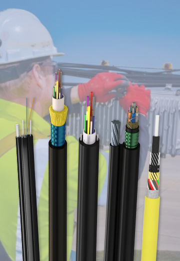 Fiber Optic Cable
 Fiber Optic Tools
 Ethernet Cable
 Coaxial Cable
 Fire & Security Cable
 Voice, Audio & Video
 Power & Control Cable