1. Distinguish a reboot from a network interruption
Record the failure time, device uptime, switch link events, PoE events and controller or camera logs before restarting anything. If device uptime continues while traffic stops, investigate the data path, VLAN, addressing and software as well as cabling. If uptime resets and the switch records a power event, power delivery becomes a stronger suspect; the event still needs interpretation because a device fault can also cause the source to remove power.
Look for repeatable triggers: camera infrared illumination, heater activation, pan-tilt movement, an AP entering a higher-power mode, or several devices starting together. A symptom correlated with temperature or time of day helps define the test conditions. Keep these as hypotheses until a controlled test reproduces the failure.
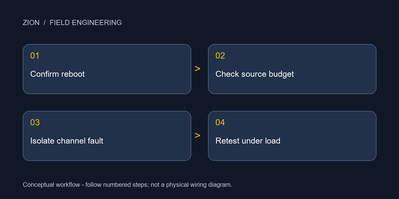
2. Check the source and power allocation
Confirm the required IEEE PoE type or vendor-specified powering method for the exact device. Check the switch port configuration, available power class, LLDP-based allocation where applicable and total budget with the actual power supplies installed. A switch can have enough capability on one port yet lack the remaining shared budget for all connected loads.
Do not equate the source’s rated output with power available at the device: the channel consumes part of that power. Verify both startup and maximum operating requirements. With an injector, confirm its power protocol and data-rate support. Use compatible standard-based equipment; an arbitrary passive injector is not a diagnostic substitute for an IEEE PoE source.
3. Change one variable at a time
Save the original configuration and label the test connections. First test the suspect device on a known-good, compatible PoE port with a short known-good cord, while reproducing its demanding operating mode. If the fault persists, focus on the device, firmware or source compatibility before replacing building cable.
If the short connection is stable, restore the installed route and substitute one accessible patch cord at a time. Then compare a known-good compatible device on the suspect route. A failure that follows the device points in a different direction from one that stays with the route. A fault that follows one switch port merits a source-side investigation. Avoid swapping device, port and cable simultaneously: that may restore service without identifying the cause.
4. Inspect connection points and the route
Disable power before opening terminations or replacing suspect connecting hardware. Inspect both RJ45 ends, patch-panel contacts, inline couplers and any outdoor junction. Look for incomplete seating, damaged latches, oxidized contacts, moisture, strain and visibly overheated material. Confirm that each plug or jack is specified for the conductor construction and diameter; a connector intended for a different wire size can make unreliable contact.
Check for crushed sections, tight ties, excessive bends, long added patch cords and unrecorded intermediate connections. In outdoor camera installations, inspect the cable entry and enclosure sealing as well as the connector itself. A thermal image can locate an unusual hot connection, but it does not certify the channel or identify resistance unbalance. Replace damaged parts and correct the cause of damage, rather than repeatedly reseating them.
5. Measure resistance and verify under load
After disconnecting active equipment as required by the tester, run the appropriate cabling certification. Add DC loop resistance and DC resistance unbalance tests within and between pairs. Poor or inconsistent terminations can produce imbalance even when a simple wire-map test passes. Select the correct channel or permanent-link test profile and retain the actual values, not only a photograph of a green PASS screen.
For a live power-delivery check, use a PoE analyzer or load test setup that supports the intended PoE type and class. Compare source allocation with power available at the far end under load. Follow equipment instructions; a no-load voltage measurement alone cannot reproduce a loaded channel. Reconnect the real device and repeat the original trigger with the expected concurrent switch load. Set the observation period to include the known failure cycle rather than an arbitrary five-minute check.
6. Replace the failed element and document the repair
If inspection and measurements identify a termination fault, choose compatible replacement hardware such as the ZION Cat6A UTP field termination plug after checking its cable fit and intended application. When the installed cable is unsuitable or damaged, use the ZION LAN/Ethernet cable catalogue to define a replacement construction; select jacket and environmental protection for the actual route. For new indoor Cat6A routes, review the U/UTP Cat6A product family and request the selected model’s electrical and project compliance documents.
Close the repair with before-and-after readings, changed part numbers, port and device identifiers, firmware/configuration records and the load conditions used. Confirm that the failure no longer appears during the agreed observation period. If the cable passes but the device still reboots on a known-good source, transfer the evidence to the equipment investigation instead of escalating cable category without a diagnosis.
Technical References
Frequently Asked Questions
Can a wire-map tester prove PoE reliability?
No. Correct continuity does not establish acceptable resistance, resistance balance or loaded power delivery.
Should every intermittent PoE fault lead to Cat6A replacement?
No. First isolate source budget, device compatibility, connectors and the installed route. Replace the element that fails the required checks.
Prepare Your Project Information
Provide equipment models, channel layout, site conditions and test records to identify suitable cabling components.



 Fiber Optic Cable
 Fiber Optic Tools
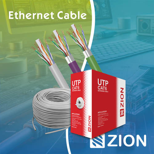 Ethernet Cable
 Coaxial Cable
 Fire & Security Cable
 Voice, Audio & Video
 Power & Control Cable