Optical Fibers Monomode G.652D
Author: James Publish Time: 19-12-2018 Origin: zion communication
G.652.D Single-Mode Fiber: Characteristics, Uses and Selection A practical guide to low-water-peak G.652.D fiber, its operating windows, applications, and the conditions that determine when G.657 bend-insensitive fiber is a better choice.
ITU-T G.652.D is a widely used low-water-peak single-mode optical fiber for telecom backbone, metropolitan, access, duct and general outdoor cable systems. It has a nominal zero-dispersion wavelength near 1310 nm, can operate in both the 1310 nm and 1550 nm regions, and extends usable transmission into the wavelength range affected by the traditional water peak. For normal routes with controlled bending, it is often the first fiber type to evaluate.
Selection rule: choose the fiber standard together with the cable construction, route geometry, splice plan, transceiver wavelength and link budget. A fiber designation alone does not determine the achievable data rate or transmission distance.
■ What Is G.652.D Single-Mode Fiber?
G.652.D is one of the fiber categories defined by ITU-T Recommendation G.652. The current Recommendation describes single-mode optical fiber and cable with zero dispersion around 1310 nm and operation in the 1310 nm and 1550 nm regions. G.652.D is similar to G.652.B but supports transmission across portions of an extended 1260–1625 nm wavelength range because its attenuation requirements include the low-water-peak region around 1383 nm.
The practical value is wavelength flexibility. Network designers can use the O band around 1310 nm and the C band around 1550 nm, while the reduced water peak also supports applications that use wavelengths between the traditional windows. The exact attenuation, chromatic dispersion, polarization-mode dispersion and geometry limits must come from the applicable fiber or cable datasheet.

■ Optical Fiber Types and Standards
Optical fibers are usually selected by transmission mode, core size, wavelength range and installation requirement. Common telecommunications categories include:
Single-mode fiber: typically 9/125 µm nominal construction, designed for long-distance and high-bandwidth transmission with compatible single-mode optics.
Multimode fiber: typically 50/125 µm for OM2, OM3, OM4 and OM5, or 62.5/125 µm for OM1. Reach depends on the optical interface, wavelength, fiber grade and data rate.
G.652 fiber: conventional single-mode fiber optimized around 1310 nm and also used around 1550 nm.
G.657 fiber: bending-loss-insensitive single-mode fiber intended for access networks, compact routing and other installations where macrobending performance is important.
G.654, G.655 and G.656 fibers: specialized single-mode categories for applications such as low-loss long-haul transmission or wavelength-division-multiplexed systems. These are not direct substitutes without system engineering review.
■ G.652.D Transmission Characteristics
Wavelength and dispersion
G.652 fiber has its zero-dispersion wavelength near 1310 nm. Attenuation is generally lower near 1550 nm, while chromatic dispersion is higher there. A complete system must therefore account for both attenuation and dispersion, especially as distance and bit rate increase.
Low-water-peak performance
Earlier fiber production could show increased attenuation near 1383 nm because of hydroxyl-ion absorption. G.652.D includes attenuation control in this region, enabling broader wavelength use and making the fiber suitable for systems that may use wavelengths between the main 1310 nm and 1550 nm windows.
Reach is a system result
Statements such as “single-mode fiber reaches 16 km or 25 km” are incomplete without the optical interface. Actual reach is determined by transmitter power, receiver sensitivity, wavelength, splice and connector losses, cable attenuation, engineering margin, dispersion tolerance and the relevant Ethernet, PON, Fibre Channel or transport specification. Use an optical link budget and the transceiver manufacturer’s limits for the final design.
■ G.652.D vs G.657.A1 and G.657.A2
The main selection difference is bend performance. G.652.D is appropriate for spacious, well-managed routes. G.657.A categories are designed for improved macrobending behavior and are useful in FTTH, indoor corners, compact terminal boxes and dense fiber management. Category A fiber retains characteristics within the G.652 framework while adding tighter macrobending requirements.
Choose G.652.D: normal outdoor, duct, backbone or access routes with controlled bend conditions and no need for compact bend optimization.
Choose G.657.A1: controlled compact routing where better bend tolerance is useful, including many indoor access and FTTH applications. Review the exact cable specification for the allowable bend radius.
Choose G.657.A2: tighter routing, denser closures, repeated handling or reel-based applications where the additional macrobending performance has a defined project value.
For current options, review ZION’s G.652.D low-water-peak single-mode optical fiber for standard routes and G.657.A1 single-mode optical fiber when controlled compact routing requires improved bend tolerance.
■ Typical Applications of G.652.D
Telecom backbone and metropolitan transmission routes
Access networks and feeder cables
Outdoor duct, direct-buried, aerial and general loose-tube cable constructions when the cable design is appropriate for the environment
Campus, industrial and building backbone links using compatible single-mode optics
Cable manufacturing projects that require a mainstream low-water-peak single-mode fiber
Fiber type does not define the complete cable. Strength members, water blocking, armor, jacket material, fire performance, installation method and environmental rating must also match the route. ZION’s optical fiber selection page organizes current fiber choices by normal routes, long-distance backbone, FTTH and higher bend-risk applications.
■ How to Specify Fiber for a Project
Before requesting a quotation or approving a cable design, prepare the following information:
Network and interface: Ethernet, PON, transport or other system; operating wavelength; transceiver type; target data rate.
Route: installed distance, splice count, connector count, pathway type and available space.
Bend conditions: minimum routing radius, closure size, reel handling and installation practices.
Cable construction: fiber count, loose-tube or tight-buffered design, armor, strength member, water blocking and jacket material.
Environment: indoor or outdoor use, duct, aerial or buried installation, temperature, moisture, UV exposure, rodent risk and applicable fire requirements.
Acceptance data: required fiber certificate, attenuation test, OTDR records, length marking, drum or reel format and delivery documentation.
■ Common Selection Mistakes
Using a fixed distance by fiber type: reach belongs to the full optical system, not the bare fiber alone.
Treating fiber bend radius as cable bend radius: the finished cable has its own installation and long-term bend limits.
Selecting only by 1310/1550 nm: dispersion, PMD, attenuation and transceiver requirements still matter.
Assuming G.657 is always better: bend-insensitive fiber adds value where bend pressure exists; normal routes may be well served by G.652.D.
Ignoring cable construction: a correct fiber grade cannot compensate for an unsuitable jacket, armor, strength member or environmental design.
■ Frequently Asked Questions
What does G.652.D mean?
It is an ITU-T G.652 category for low-water-peak single-mode fiber. It retains the conventional G.652 operating concept around 1310 nm and 1550 nm while controlling attenuation in the extended wavelength region.
Is G.652.D the same as OS2?
No. G.652.D is an ITU-T fiber category, while OS2 is a cabled-fiber designation used in premises cabling standards. A product may be designed to meet both relevant requirements, but the terms are not interchangeable without checking the product specification.
Can G.652.D be used at 1550 nm?
Yes. G.652 fiber can be used in the 1550 nm region. The link design must account for chromatic dispersion, attenuation, equipment specifications and the planned transmission distance.
When should G.657.A1 be selected instead?
Use G.657.A1 when FTTH, indoor corners, compact terminals or other controlled small-radius routes create a meaningful bend-loss risk. Confirm the finished cable’s bend specification rather than applying a bare-fiber value to the entire cable.
How is transmission distance calculated?
Start with the transceiver’s permitted reach and optical power budget, then subtract fiber attenuation, connector loss, splice loss and engineering margin. Check dispersion and any protocol-specific limits before approving the final distance.



 Fiber Optic Tools
Products 6 families
Solutions 6 markets
Resources Tools & docs
Certificate
Certification and compliance references for project review, qualification and purchasing documentation.

 Fiber Optic CableAccess and backbone
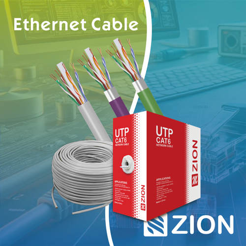 Ethernet CableCat5e to Cat8
 Coaxial CableRF and video signal
 Fire, Security & AlarmSafety systems
 Voice, Audio & VideoSignal cabling
 Power & Control CableEnergy and control
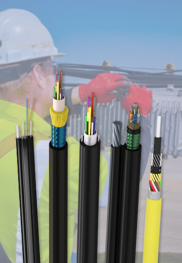
Fiber optic cable systems
Outdoor, indoor, FTTH and distribution cable lines for access networks, backbone routes and campus deployments.
 Telecom & ISP NetworksFTTH, PON, ODN
 Data Center InfrastructureServer room cabling
 Building Low-Voltage SystemsBMS, AV, weak current
 Security & Fire ProtectionAlarm, CCTV, access
 Industrial Automation CablePLC, RS485, fieldbus
 Energy & Power InfrastructureSolar, battery, power
Telecom & ISP Networks
For FTTH / PON access, outdoor fiber deployment, aerial routes, duct routes, direct burial routes, rural broadband and ODN planning.
Tools
Use calculators and planning tools for conduit capacity, PoE voltage drop and fiber optic link loss budget work.