Tips about Fiber Optic Connectors - You need to know
Author: Site Editor Publish Time: 20-01-2021 Origin: Site
Fiber Optic Connector Types and Selection Guide Compare LC, SC, FC, ST, MPO and other connector formats, understand PC, UPC and APC end-face polishes, and identify the interface details needed for a reliable fiber link.
What Is a Fiber Optic Connector?
A fiber optic connector creates a demountable optical joint between fibers or between a fiber cable and equipment. Its ferrule, housing and coupling mechanism align the fiber cores while allowing the connection to be installed, removed and serviced.
Connector selection affects optical performance, panel density, handling, polarity and maintenance. The correct choice is not determined by connector shape alone. A buyer must match the equipment interface, fiber type, ferrule polish, loss budget, environment and required test documentation.
Important: Ferrule size depends on the connector family. LC and MU commonly use a 1.25 mm cylindrical ferrule; SC, FC and ST commonly use a 2.5 mm ferrule; MPO uses a rectangular multi-fiber MT ferrule.
Insertion Loss, Return Loss and Reflectance
Insertion loss is the optical power lost as light passes through a mated connection. It is expressed as a positive dB value, and lower is better.
Return loss describes how effectively the connection limits reflected power. It is normally expressed as a positive dB value, and higher is better. Reflectance describes the reflected power at a specific event and is commonly shown as a negative dB value, where a more negative value indicates less reflection.
Do not compare a negative reflectance value directly with a positive return-loss specification without checking the measurement convention. The loss budget for a complete link can include fiber attenuation, connector loss, splice loss, splitters and other passive components; no single element is always the largest contributor.
PC, UPC and APC Connector Polish
PC, UPC and APC describe ferrule end-face geometry and polishing, not connector families. For example, SC or LC connectors may be supplied with different polish options when the interface supports them. Representative return-loss values are useful for comparison, but the qualified component specification and test report should control the final design.
PC: Physical Contact

PC polishing creates a convex surface so the fiber cores make physical contact and reduce the air gap. Typical return loss is often around 30-40 dB, depending on the connector, termination quality and test method. PC terminology is still encountered, particularly in multimode and legacy systems, although UPC or APC is often specified for modern single-mode assemblies.
UPC: Ultra Physical Contact

UPC uses an improved convex polish and surface finish to reduce reflection compared with a basic PC finish. Representative return loss is commonly around 40-50 dB or better. UPC is widely used for digital telecom, enterprise and data applications where low insertion loss and moderate reflection control are required.
APC: Angled Physical Contact

APC normally uses an 8° angled end face. Reflected light is directed away from the core, allowing much higher return loss than a non-angled finish. Representative return loss is often 60 dB or higher. APC is common in PON/FTTx, analog or RF-over-fiber links and other single-mode systems that are sensitive to reflection.
UPC vs APC: How to Choose
Choose UPC when the equipment interface specifies a non-angled physical-contact connector and the link does not require the reflection performance of APC. Choose APC when the transceiver, splitter, instrument or network architecture requires an angled interface and higher return loss.

End face: UPC uses a convex non-angled polish; APC uses an angled physical-contact polish.
Color: Green commonly identifies APC, while blue commonly identifies single-mode UPC. Color conventions are helpful but should not replace the connector label, equipment documentation or end-face verification.
Do not mate APC directly with UPC or PC. The end faces do not match correctly, which can create high insertion loss, high reflection and possible end-face damage.
Eight Fiber Optic Connector Formats
The best connector format is the one that matches the installed hardware and project requirements. LC and SC dominate many current enterprise, telecom and access-network deployments; MPO supports multi-fiber high-density links; the remaining formats are important in particular installed bases or specialty systems.
LC Connector

LC is a small-form-factor, latched connector with a 1.25 mm ferrule. Its compact size suits high-density patch panels, data-center equipment and transceiver interfaces. Confirm simplex or duplex format, fiber type and polish.
SC Connector

SC uses a push-pull coupling and a 2.5 mm ferrule. It is widely used in telecom rooms, ODFs, FTTH/PON equipment and enterprise networks. SC is physically larger than LC but easy to handle and identify.
FC Connector

FC uses a threaded coupling and a keyed 2.5 mm ferrule interface. It remains useful in test, measurement, laboratory and some vibration-sensitive installations, although LC and SC are more common in many modern communication panels.
ST Connector

ST uses a spring-loaded bayonet coupling and a 2.5 mm ferrule. It is still found in legacy multimode LAN, campus and industrial installations. New projects should confirm whether existing ST hardware must be retained or converted with a hybrid assembly.
MT-RJ Connector

MT-RJ places two fibers in one compact MT-style ferrule and uses alignment pins. It appears mainly in legacy or specialized duplex systems. Test-set adapters and male/female pin configuration should be checked before ordering replacement cords.
MU Connector

MU is a compact push-pull connector with a 1.25 mm ferrule. Its footprint supports dense equipment layouts, but it is less widely deployed globally than LC. Confirm availability of compatible adapters, tools and replacement assemblies.
E-2000 Connector

E-2000 is a push-pull connector with an integrated spring-loaded shutter that protects the end face from dust and scratches when unmated. It is used in selected telecom, metrology, medical, rail and industrial systems. Check the precise interface, polish and supplier data sheet rather than relying on the housing name alone.
MPO Connector

MPO is a standardized multi-fiber push-on interface used for high-density trunks and parallel-optics cabling. MTP is a US Conec brand of MPO connector. A usable specification must identify fiber count, fiber type, key orientation, polarity method and whether the connector requires guide pins or guide-pin holes. Do not assume every 12- or 24-fiber MPO assembly has the same mapping.
Ferrules, Alignment and End-Face Care
Many single-fiber connectors use precision zirconia ceramic ferrules because the material can maintain a stable, accurately formed bore. MPO connectors instead use a molded rectangular MT ferrule and precision guide pins or guide-pin holes to align multiple fibers. Adapter sleeves may use ceramic or metal depending on the interface and product design.

Dust, oil and scratches can increase loss and reflection. Use the inspect-clean-inspect process with tools that match the connector and follow laser-safety procedures. IEC 61300-3-35 defines visual inspection criteria, but visual inspection does not replace optical performance testing.
Fiber Connector Selection Checklist
1. Equipment interface: Record the connector family and whether the port is UPC, APC or another specified finish.
2. Fiber type: Confirm single-mode or multimode and the exact OS/OM grade required by the link.
3. Link design: Define simplex, duplex or multi-fiber transmission, required polarity and any breakout mapping.
4. Optical budget: Specify maximum insertion loss and minimum return loss for the assembly and complete link.
5. Mechanical requirements: Check panel density, latch or coupling style, cable diameter, boot length, bend control and service access.
6. Environment and compliance: Define temperature, indoor/outdoor use, jacket rating, contamination exposure and applicable project standards.
7. Testing and documentation: State whether individual insertion-loss and return-loss results, end-face inspection records, labels or polarity reports are required.
For available formats and current product options, review ZION's fiber optic connector range and confirm the final specification against the equipment and link design.
Frequently Asked Questions
What is the most common fiber optic connector?
LC and SC are among the most common current single-fiber formats. LC is favored where port density matters, while SC remains common in telecom, ODF and FTTH/PON installations. The equipment port determines the required interface.
Is APC better than UPC?
APC normally provides better reflection performance, but it is not automatically the correct choice. Use the polish required by the equipment and link. UPC and APC should not be directly mated.
What is the difference between MPO and MTP?
MPO is the standardized multi-fiber interface family. MTP is a registered US Conec brand of MPO connector with proprietary mechanical design features. Both still require a complete fiber-count, polarity, key-orientation and pin specification.
Can connector color alone identify UPC or APC?
No. Green commonly indicates APC and blue commonly indicates single-mode UPC, but color alone is not enough. Confirm the label, end-face type and equipment documentation before mating connectors.
Selection summary: Start with the equipment port and fiber type, then confirm polish, density, polarity, optical performance, environment and test requirements. A connector is suitable only when all of these conditions match the link.



 Fiber Optic Tools
Products 6 families
Solutions 6 markets
Resources Tools & docs
Certificate
Certification and compliance references for project review, qualification and purchasing documentation.
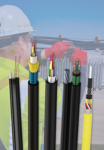 Fiber Optic CableAccess and backbone
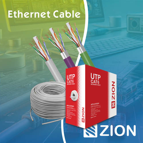 Ethernet CableCat5e to Cat8
 Coaxial CableRF and video signal
 Fire, Security & AlarmSafety systems
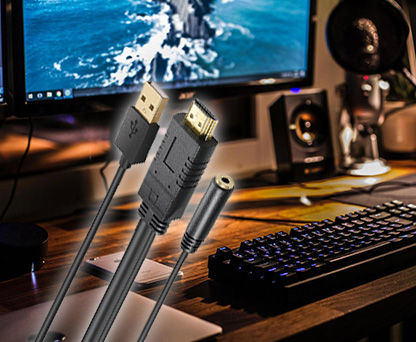 Voice, Audio & VideoSignal cabling
 Power & Control CableEnergy and control
Fiber optic cable systems
Outdoor, indoor, FTTH and distribution cable lines for access networks, backbone routes and campus deployments.
 Telecom & ISP NetworksFTTH, PON, ODN
 Data Center InfrastructureServer room cabling
 Building Low-Voltage SystemsBMS, AV, weak current
 Security & Fire ProtectionAlarm, CCTV, access
 Industrial Automation CablePLC, RS485, fieldbus
 Energy & Power InfrastructureSolar, battery, power
Telecom & ISP Networks
For FTTH / PON access, outdoor fiber deployment, aerial routes, duct routes, direct burial routes, rural broadband and ODN planning.
Tools
Use calculators and planning tools for conduit capacity, PoE voltage drop and fiber optic link loss budget work.