What is POE & how to chose right cable for POE?
Author: michael Publish Time: 23-07-2019 Origin: Site
What Is PoE and How Do You Choose the Right Ethernet Cable? A practical guide to PoE standards, cable construction, heat, distance, installation conditions, and project checks.
Power over Ethernet (PoE) carries low-voltage DC power and Ethernet data over the same balanced twisted-pair cabling. A PoE system includes power sourcing equipment (PSE), such as a PoE switch or midspan injector, a powered device (PD), such as an IP camera or wireless access point, and the cabling channel between them. The right cable is not selected by category alone: the device power requirement, Ethernet speed, channel length, conductor construction, bundle size, ambient temperature, pathway, and local code requirements all matter.
What Is PoE and How Does It Work?
In standards-based PoE, the PSE first detects whether a valid PD is connected. It then classifies the power requirement, applies power, and monitors the connection. If the PD is disconnected, draws excessive power, or the link develops a short circuit, a compliant PSE can remove power from the port. This controlled process distinguishes IEEE 802.3 PoE from passive or proprietary powering methods that may apply voltage without the same detection process.

PoE can simplify installation because a separate local power outlet is not required at every endpoint. It can also centralize power management and allow selected devices to remain available through a suitably designed uninterruptible power supply. These advantages do not remove the need for correct network design, electrical safety practices, building-code compliance, and equipment compatibility checks.
PoE Types and Available Power
IEEE PoE types are often marketed as PoE, PoE+, or PoE++, but the IEEE type and class are the more useful design references. The maximum power at the PSE output is higher than the power guaranteed at the PD because the cabling channel has electrical losses.
Type 1 — IEEE 802.3af
Uses two powered pairsets and supports up to 15.4 W at the PSE, with up to 13 W available to the PD under the standard channel model.
Type 2 — IEEE 802.3at
Uses two powered pairsets and supports up to 30 W at the PSE, with up to 25.5 W available to the PD.
Type 3 — IEEE 802.3bt
Can use four powered pairsets and supports up to 60 W at the PSE, with up to 51 W available to a single-signature PD at the highest Type 3 class.
Type 4 — IEEE 802.3bt
Uses four powered pairsets and supports up to 90 W at the PSE, with up to 71.3 W available to a single-signature PD at Class 8.
Always compare power figures at the same reference point. A switch port labeled with a PSE output value does not mean the PD receives that entire amount. Also confirm the switch's total PoE budget when several ports will be powered simultaneously.
Which Devices Commonly Use PoE?
PoE is widely used where network connectivity and centralized power are both valuable. Typical devices include:
IP cameras and video intercoms
VoIP telephones
Wireless access points
Access-control readers and selected controllers
Network speakers, sensors, lighting controllers, and building-automation endpoints

How to Choose the Right Ethernet Cable for PoE
1. Start with the device, PoE type, and data rate
Record the PD model, its required PoE type or class, maximum input demand, and Ethernet speed. Cat5e may support many standards-based PoE applications when the complete channel meets the applicable requirements, but Cat6 or Cat6A can provide more design margin for new installations. Cat6A is a practical choice when 10GBASE-T, higher-density pathways, or future network upgrades are part of the project. ZION's LAN and Ethernet cable catalog provides Cat5e, Cat6, Cat6A, and other construction options for comparison.
2. Specify conductor material and size
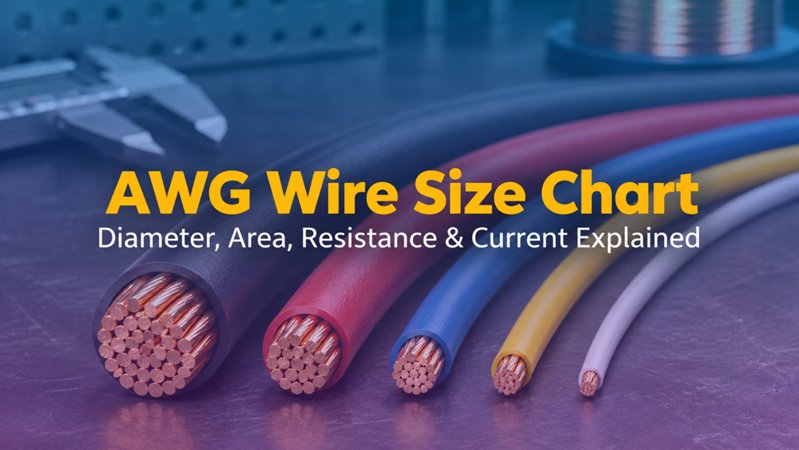
Request the actual conductor material, gauge, and solid or stranded construction. For otherwise comparable copper conductors, a smaller cross-section has higher resistance per unit length, which increases voltage drop and heating. Solid conductors are normally used for fixed horizontal cabling, while stranded conductors provide flexibility for equipment cords. Copper-clad aluminum is not equivalent to a solid or stranded bare-copper conductor specification and should not be substituted without an engineering and compliance review.
3. Evaluate the complete channel, not one cable segment
Include horizontal cable, patch cords, connectors, patch panels, consolidation points, and the number of connections. Longer channels and additional contact interfaces add resistance. Confirm the permitted topology and length for the required Ethernet application and the selected cabling components. A short patch cord cannot compensate for an out-of-spec permanent link.
4. Check bundle size and temperature
Current flowing through conductors produces heat. The temperature rise depends on current, conductor resistance, cable construction, the number of powered cables in a bundle, pathway ventilation, and ambient temperature. Higher temperature also increases copper resistance and can reduce data-transmission margin. Use the project code, cabling standard, manufacturer guidance, and actual installation conditions to determine bundle limits or derating; do not apply one universal bundle number to every design.
5. Match shielding to the environment
Shielding is selected for electromagnetic compatibility and pathway conditions, not simply because a link uses PoE. Shielded cabling requires compatible connecting hardware and a properly designed bonding and grounding approach. In interference-prone fixed installations, a product such as ZION's Cat6A S/FTP solid-copper installation cable may be relevant when its jacket, temperature, fire-performance, and documentation fit the project.
6. Select the correct jacket and pathway rating
Indoor, riser, plenum, low-smoke, outdoor, duct, direct-burial, UV, moisture, oil, and industrial routes can require different cable constructions. The Ethernet category does not define all environmental or fire-performance properties. Confirm the exact part number and supporting documents for the installation location and target market.
7. Treat slim patch cords as a separate design decision
Slim cords can improve airflow and port access in dense cabinets, but their conductor size, cord length, bundle conditions, and supplier-declared channel limits must be reviewed for the intended PoE load. Check the application conditions on the exact product, such as ZION's Cat6A 28 AWG slim patch cord, rather than assuming that every cord with the same category label has identical remote-power limits.
Common PoE Cable Selection Mistakes
Using only the category label: Cat6 or Cat6A does not by itself confirm conductor material, gauge, jacket rating, bundle conditions, or compatibility with a specific PoE load.
Confusing PSE power with PD power: cable losses mean the guaranteed power at the device is lower than the maximum output at the source.
Ignoring the switch power budget: each port may support the required class while the total switch budget remains insufficient for all connected devices.
Assuming link-up proves compliance: a device turning on does not demonstrate full data performance, thermal suitability, resistance balance, or long-term operation under the intended load.
Overlooking connectors: termination quality, contact condition, component ratings, and DC resistance unbalance can affect both power delivery and network performance.
PoE Cable Specification Checklist
Before requesting a quotation or approving a cable, prepare the following information:
Powered-device models, quantity, required PoE type or class, and data rate
PSE model, per-port capability, and total available power budget
Permanent-link and channel lengths, patch-cord lengths, and connection count
Cable category, conductor material, gauge, and solid or stranded construction
Powered bundle size, ambient temperature, enclosure, and ventilation conditions
Shielding, bonding, grounding, and electromagnetic-interference conditions
Indoor, outdoor, riser, plenum, low-smoke, UV, moisture, oil, or burial requirements
Required standards, market approvals, test records, and project acceptance criteria
Frequently Asked Questions
Is Cat5e suitable for PoE?
Cat5e can support many IEEE PoE applications when the complete channel meets the applicable cabling and PoE requirements. Confirm conductor construction, resistance, length, temperature, bundling, connectors, and the required data application. For new projects, Cat6 or Cat6A may provide more design margin or upgrade flexibility.
Does PoE always require shielded cable?
No. Shielding is chosen for the electromagnetic environment and system design. Many PoE links use unshielded cabling. When shielded cable is specified, use compatible components and follow the project's bonding and grounding design.
Can any Cat6A cable be used for Type 4 PoE?
Do not decide from the category marking alone. Verify the exact cable and connecting hardware, conductor resistance and unbalance, channel arrangement, bundle size, ambient temperature, jacket rating, equipment class, and supplier-declared application limits.
Is a powered device turning on enough to accept the installation?
No. Complete the project-defined cabling and PoE checks using suitable test equipment and acceptance criteria. Retain results against the installed link identity, especially when higher power, long channels, dense bundles, or challenging environments are involved.



 Fiber Optic Tools
Products 6 families
Solutions 6 markets
Resources Tools & docs
Certificate
Certification and compliance references for project review, qualification and purchasing documentation.
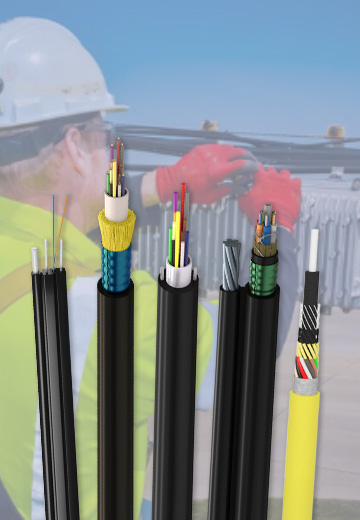 Fiber Optic CableAccess and backbone
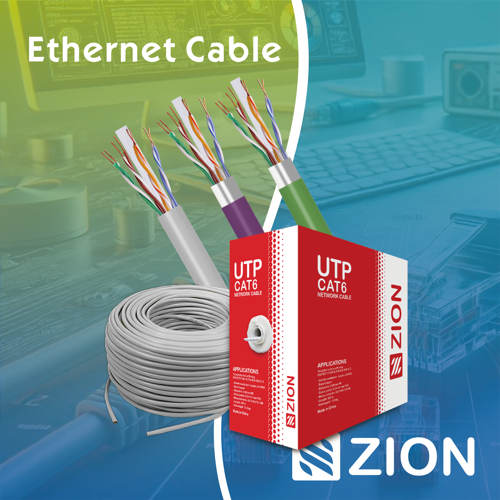 Ethernet CableCat5e to Cat8
 Coaxial CableRF and video signal
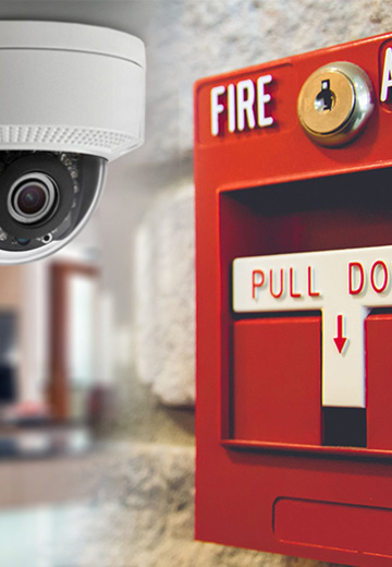 Fire, Security & AlarmSafety systems
 Voice, Audio & VideoSignal cabling
 Power & Control CableEnergy and control
Fiber optic cable systems
Outdoor, indoor, FTTH and distribution cable lines for access networks, backbone routes and campus deployments.
 Telecom & ISP NetworksFTTH, PON, ODN
 Data Center InfrastructureServer room cabling
 Building Low-Voltage SystemsBMS, AV, weak current
 Security & Fire ProtectionAlarm, CCTV, access
 Industrial Automation CablePLC, RS485, fieldbus
 Energy & Power InfrastructureSolar, battery, power
Telecom & ISP Networks
For FTTH / PON access, outdoor fiber deployment, aerial routes, duct routes, direct burial routes, rural broadband and ODN planning.
Tools
Use calculators and planning tools for conduit capacity, PoE voltage drop and fiber optic link loss budget work.