What is the CATV Line Amplifier?
Author: James Xu Publish Time: 19-11-2018 Origin: Site
What Is a CATV Line Amplifier? How It Works and How to Choose
A practical guide to gain, equalization, return-path support, powering, installation conditions, and the information required to specify an amplifier for a coaxial distribution network.
A CATV line amplifier—also called a trunk or distribution amplifier—is an active RF device installed in a 75-ohm coaxial network to raise signal level and compensate for frequency-dependent loss. It can extend a properly engineered distribution route, but it cannot recover information already lost to noise, severe distortion, ingress, damaged cable, or poor connectors. Correct selection therefore starts with a level and loss budget, not with distance alone.
What Does a CATV Line Amplifier Do?
Coaxial cable attenuation increases with cable length and normally rises with frequency. Splitters, taps, connectors, and passive devices add more insertion loss. A line amplifier provides controlled forward-path gain to restore the planned RF level and uses equalization to compensate for the greater loss at higher frequencies. In a two-way network, a separate return path carries upstream signals through the appropriate low-frequency band.
An amplifier should be placed where measured or calculated levels require it. There is no universal cable length—such as 100 metres—at which every CATV system needs amplification. Cable type, frequency, temperature, passive losses, input level, required output level, noise and distortion limits all affect the decision.
How a CATV Line Amplifier Works
A common amplifier signal path combines attenuation, equalization, low-noise gain and output gain stages. The exact architecture varies by model, but each function serves a distinct purpose:
Input attenuation reduces an excessive input level so the amplifier operates within its intended range.
Input equalization adjusts the tilt or slope across the forward band before amplification.
Preamplification adds initial gain while protecting the system noise figure as far as the design permits.
Interstage controls set internal level and slope so later stages are not overdriven.
Output amplification delivers the level required to feed the next section of the distribution plant.
Diplex filtering separates forward and return bands in a bidirectional design so downstream and upstream signals follow the correct paths.
Attenuation before gain is not wasted amplification. It provides level control and headroom, while equalization shapes the spectrum before the active stages. This helps the technician achieve the target output without exceeding the amplifier's linear operating region.

Key Specifications to Compare
Forward and return frequency ranges
The amplifier band split must match the network architecture. Compare the exact forward and return frequency ranges, not only the headline upper frequency. A device intended for one split cannot be assumed to support another upstream allocation.
Gain, slope and adjustment range
Maximum gain is not the same as usable system gain. Confirm the required gain at the design frequencies, the available attenuator and equalizer range, and the expected cable-loss change with temperature. The final setting should follow measured input and output levels.
Output level and distortion performance
The permissible output depends on loading conditions, channel plan and the measurement method stated in the data sheet. Composite second-order and triple-beat figures may be relevant to analogue loading, while digital services also require suitable modulation-error, carrier-to-noise and linearity performance. Compare values only when test conditions are equivalent.
Powering and environmental rating
Verify the actual power method, voltage range, consumption, surge protection, grounding and bonding requirements. For outdoor plant, check enclosure sealing, corrosion resistance, operating temperature, mounting method and connector weatherproofing. Do not infer the power input or environmental rating from a visually similar housing.

How to Choose the Right Amplifier
Define the network bands. Record the forward range, return range and required diplex split.
Build the RF loss budget. Include the selected cable's attenuation at the highest relevant frequency plus losses from taps, splitters, connectors and other passives.
Confirm level and slope targets. State measured input levels, desired output levels, expected tilt and the required adjustment range.
Check loading and linearity. Provide the channel or carrier plan and the performance criteria used by the operator.
Choose one-way or two-way operation. A return path is required for upstream services; confirm both its frequency range and gain.
Match power and installation conditions. State line power or local power, indoor or outdoor use, temperature, mounting, grounding, bonding and connector requirements.
Verify the complete data sheet. Treat catalogue examples as orientation only and obtain the exact model's limits, test conditions and installation instructions.
The amplifier and the coaxial plant must be specified together. ZION's 75-ohm CATV coaxial cable range helps identify suitable drop, distribution and trunk cable families for the route. Use the chosen cable's attenuation data—not a generic distance rule—in the system calculation.
For subscriber drops and shorter distribution sections, review the available RG6 CATV cable constructions. For main distribution routes, compare the mechanical and attenuation characteristics of trunk and hardline coaxial cable before fixing amplifier spacing and gain.
Common CATV Line Amplifier Types
One-way amplifiers amplify only the forward path and suit systems with no upstream service.
Bidirectional amplifiers provide forward and return paths with a defined band split.
Indoor amplifiers are intended for protected environments and local distribution.
Outdoor line or trunk amplifiers use weather-resistant housings and installation hardware appropriate to outside plant.
Manual-control models use technician-set gain and equalization; automatic-control models may regulate level or slope within the limits stated by the manufacturer.

Installation and Commissioning Checks
Measure forward and return levels before and after the amplifier with calibrated equipment.
Set attenuation and equalization from the design targets; do not default every control to maximum gain.
Confirm connector type, preparation, torque, weather sealing and cable bend radius.
Follow the manufacturer and network operator requirements for bonding, grounding, surge protection and power isolation.
Check the complete route for damaged cable, loose connectors, excessive passive loss and ingress before adding gain.
Record final settings and measurements so later maintenance can distinguish plant changes from amplifier faults.

Information to Provide Before Ordering
A supplier or system designer can evaluate the requirement more accurately when the request includes:
forward and return frequency ranges;
measured input level and required output level by frequency;
required gain, slope and adjustment range;
channel or carrier loading and applicable performance criteria;
cable type, route length, passive-device losses and planned amplifier location;
power method and voltage range;
indoor or outdoor environment, temperature range and enclosure requirement;
number and type of RF ports, connectors and mounting arrangement.
Frequently Asked Questions
Does a CATV amplifier improve every weak signal?
No. It raises signal and noise together and can add its own noise and distortion. Repair cable, connector, ingress and passive-loss problems before using amplification to meet a calculated level budget.
What is the difference between gain and equalization?
Gain raises the signal level. Equalization changes the level by frequency to offset cable tilt, which is usually greater at higher frequencies.
When is a return-path amplifier required?
It is required when the network carries upstream traffic and passive return loss cannot meet the level plan. The return band, gain and noise performance must match the system split and design.
Can amplifier spacing be selected by cable length alone?
No. Spacing depends on cable attenuation by frequency, temperature, passive losses, input level, output limit, slope, noise accumulation and distortion budget.
Can an example specification be used for purchasing?
Only as an initial reference. The exact model data sheet should confirm frequency bands, gain, output performance, powering, environmental limits, ports and test conditions before an order is placed.



 Fiber Optic Tools
Products 6 families
Solutions 6 markets
Resources Tools & docs
Certificate
Certification and compliance references for project review, qualification and purchasing documentation.

 Fiber Optic CableAccess and backbone
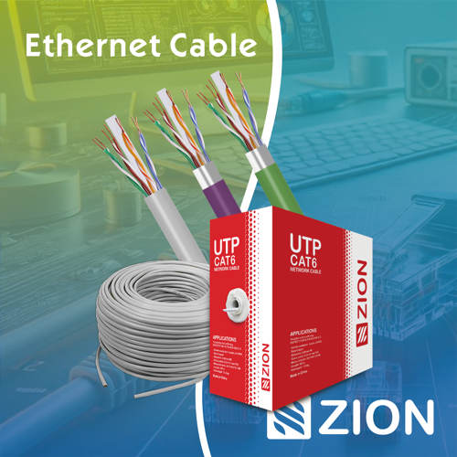 Ethernet CableCat5e to Cat8
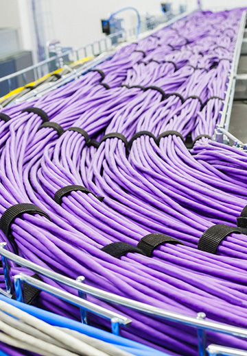 Coaxial CableRF and video signal
 Fire, Security & AlarmSafety systems
 Voice, Audio & VideoSignal cabling
 Power & Control CableEnergy and control
Fiber optic cable systems
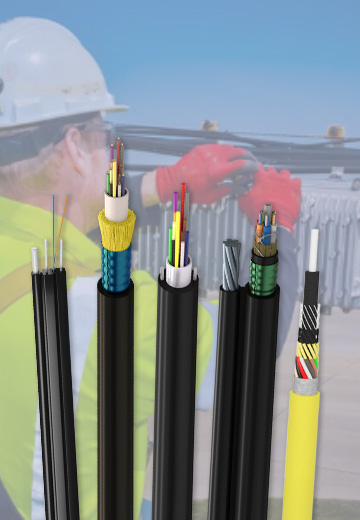
Outdoor, indoor, FTTH and distribution cable lines for access networks, backbone routes and campus deployments.
 Telecom & ISP NetworksFTTH, PON, ODN
 Data Center InfrastructureServer room cabling
 Building Low-Voltage SystemsBMS, AV, weak current
 Security & Fire ProtectionAlarm, CCTV, access
 Industrial Automation CablePLC, RS485, fieldbus
 Energy & Power InfrastructureSolar, battery, power
Telecom & ISP Networks
For FTTH / PON access, outdoor fiber deployment, aerial routes, duct routes, direct burial routes, rural broadband and ODN planning.
Tools
Use calculators and planning tools for conduit capacity, PoE voltage drop and fiber optic link loss budget work.