
This article covers accessible, field-serviceable optical connections. Internal optical assemblies and interfaces that are not intended for field cleaning require the equipment manufacturer's service procedure.
1. Start with the Optical Interface, Not Just the Data Rate
800G and 1.6T are relevant to current AI networking product discussions. NVIDIA's LinkX portfolio lists 800G and 1.6T options and both 100G- and 200G-per-lane PAM4 technologies. This establishes product relevance, not the proportion of data centers using each technology. NVIDIA LinkX portfolio
Neither aggregate data rate specifies a universal connector, lane arrangement, or optical loss budget. A higher headline speed does not, by itself, tell you how much loss a contaminant will introduce or how much margin the installed channel has left.
Before selecting cabling and fiber optic cleaning tools, identify:
- The transceiver part numbers, application, reach, and optical lane arrangement.
- The fiber type and exact optical connector interface at each end.
- The permitted channel insertion loss and applicable reflection limits.
- The planned connections, splices, and engineering margin.
- The access and tooling needed to inspect and clean each serviceable interface.
Do not treat an OSFP or QSFP form factor as a complete specification of the optical connector. Confirm the mating interface from the exact product documentation. When comparing Hello Signal 800G OSFP transceivers, check the connector and reach for the selected model.
Cleaning removes an avoidable source of impairment. It cannot correct incompatible optics, incorrect polarity, or a channel that exceeds its specified loss limit.
2. Understand Loss, Reflection, and Physical Damage
Particles, oils, fingerprints, and residues can interfere with optical transmission. At a physical-contact connection, debris can also prevent proper contact or damage mating surfaces. Cisco fiber inspection and cleaning guidance
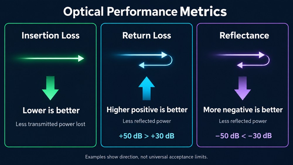
Keep these three measurements distinct:
| Parameter | Meaning | Preferred direction |
|---|---|---|
| Insertion loss | Reduction in transmitted optical power through a component or channel | Lower, within the specified limit |
| Return loss | Ratio of incident power to reflected power, expressed in dB | Higher positive value means less reflection |
| Reflectance | Ratio of reflected power to incident power, expressed in dB | More negative value means less reflection |
Return loss is −10 log₁₀(reflected power / incident power). A return loss of 50 dB corresponds to a reflected fraction of 0.001%; 30 dB corresponds to 0.1%. These are illustrations of the definition, not acceptance thresholds for every connector. For the same reflection measurement, the equivalent reflectance values are −50 dB and −30 dB. Fluke Networks: return loss and reflectance
An individual connection measurement and whole-link optical return loss have different scopes. Record what was measured and under which conditions.
Cleaning does not repair chips or damaged polish. If a suspected defect remains, escalate for evaluation or replacement under the agreed acceptance procedure rather than treating repeated cleaning as a repair.
3. Inspect the Contact Area, Not Just One Fiber
For multi-fiber connectors, a clean image of one fiber is insufficient. Inspection must cover the fiber end faces and the contact area required by the applicable criteria. IEC 61300-3-35:2022 explicitly includes contamination inspection of the whole ferrule surface for rectangular ferrules. IEC 61300-3-35:2022
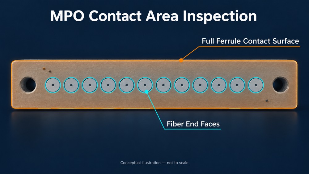
Choose a probe, adapter, field of view, and analysis profile suitable for the actual connector. Check that the inspection workflow covers the complete required area; an automated pass result is only meaningful for the area and criteria evaluated.
Unused fiber positions do not make the surrounding contact surface irrelevant. Debris can transfer between mating interfaces. Protective caps also do not certify cleanliness: factory-tested and capped assemblies still require preconnection inspection. ZION: MPO connector cleaning and inspection
Manufacturer requirements can be more specific. NVIDIA's DGX SuperPOD NDR cabling guide requires cleaning both the MPO connector and the transceiver receptacle before every insertion, including reinsertion after accidental detachment. Apply that requirement to the equipment it covers; use the corresponding instructions for other platforms. NVIDIA: maintaining NDR connectors and cables
4. Separate Link Impairment from Application Impact
Contamination is one possible cause of an impaired optical path. Its operational effect depends on severity, the transceiver, error correction, the fabric, and the workload.
Forward error correction (FEC) can correct some transmission errors. Corrected-error activity alone does not establish packet loss, reduced application throughput, or a dirty connector. Where supported, examine pre-FEC indicators, uncorrectable errors, and link-state changes over a defined interval. Interpret counters using the equipment documentation and the relevant operating limits. NVIDIA's troubleshooting guidance distinguishes corrected errors from errors that remain after FEC and recommends checking changes over time. NVIDIA: Layer 1 troubleshooting
If an impairment produces uncorrectable errors or link failures, workload effects can include interrupted communication, recovery activity, or delayed completion. Their extent depends on redundancy and workload behavior. One dirty connector does not necessarily stop an entire cluster.
For business planning, use the site's own records: troubleshooting hours, repeated acceptance work, delayed deployment, and affected jobs. A generic downtime figure or contamination percentage would not establish the financial exposure of a particular AI facility.
5. Use an Inspect–Clean–Reinspect Workflow
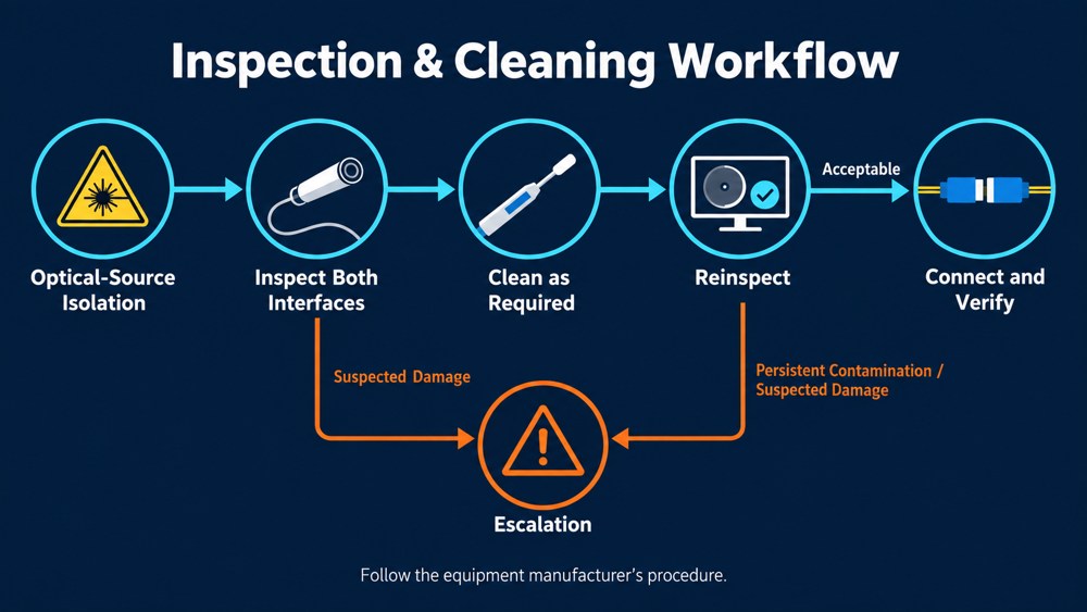
- Prepare safely. Identify the connection and maintenance window. Disable or isolate optical sources as required by the equipment procedure before inspection or cleaning. Do not look directly into an active fiber.
- Inspect both accessible mating interfaces. Use the correct video probe and adapter. If an interface cannot be inspected with available tooling, follow the equipment service procedure rather than attempting blind cleaning.
- Clean according to the applicable procedure. Use a compatible tool and fresh cleaning media. Follow any manufacturer requirement to clean before every insertion.
- Reinspect. Verify the cleaned interface before mating. Escalate persistent contamination or suspected damage through the approved maintenance process.
- Reconnect and verify. Complete the required checks and record the outcome against the link identifier.
Cisco describes dry cleaning followed by inspection, with wet-to-dry escalation where appropriate; it cautions against wet cleaning equipment receptacles. Do not transfer a patch-cord cleaning method to a transceiver port without manufacturer approval. Cisco maintenance procedure
Clean and protect inspection adapters and test reference leads as well, since they can transfer contamination. FOA guidance for test equipment and cables
Build these controls into installation, reconnection, planned changes, and fault investigation. Establish maintenance triggers in the site procedure; avoid unnecessary disconnection of healthy links solely to perform calendar-based cleaning.
6. Keep Visual, Cabling, and Operational Evidence Separate
IEC 61300-3-35:2022 states that visual inspection does not replace attenuation, return-loss, or end-face parameter measurements. Its public summary also cautions against rejecting a connector solely because it fails visual inspection. A persistent visual finding therefore requires disposition under the applicable performance and acceptance requirements, rather than an automatic assumption that the connector is unusable. IEC standard summary
An acceptance plan should distinguish the evidence below. For MPO-specific checks, see ZION's MPO fiber testing and acceptance guide.
| Evidence | What to record |
|---|---|
| End-face inspection | Connector identity, image, inspection profile and standard edition, result, and any unresolved finding |
| Cabling verification | Fiber mapping and polarity, continuity, insertion loss at the specified wavelengths and reference method, and reflection measurements where required |
| Active-link validation | Intended equipment and configuration, relevant optical diagnostics, error-counter changes, link stability, and the agreed traffic or workload test |
Define the limits and methods before testing. An inspection image does not establish channel loss, and a link-up indicator does not demonstrate performance under the intended workload.
These are project acceptance requirements to agree with the responsible teams, not a claim that every deployment needs the same instruments or test suite.
7. Make Maintenance Readiness Part of the Cabling Brief
When discussing fiber connectivity with ZION, provide the transceiver models, link distances, connector interfaces, fiber mapping, panel layout, and acceptance requirements.
Use that brief to confirm the proposed assembly specifications and the evidence required for the order:
- Fiber type, connector format, fiber count, polish, and polarity; MPO pin configuration where applicable.
- Agreed insertion-loss and reflection limits, with measurement conditions.
- Required factory records and their traceability to the supplied assemblies.
- Compatible inspection and cleaning tools, along with physical access at the panel.
- Labeling, spare assemblies, and handover documentation.
Confirm the availability of each requested record or service for the selected ZION product and quotation. Factory results support delivery acceptance; the final installed channel still needs its own agreed verification.
Reliable AI connectivity depends on compatible components, a channel within specification, and well-controlled installation. Fiber inspection and cleaning support all three by making the condition of each serviceable optical interface part of the deployment process.
Prepare Your Fiber Connectivity Brief
Share transceiver models, link distances, connector interfaces, fiber mapping, panel layout, and acceptance requirements with ZION.
Request Project Support


