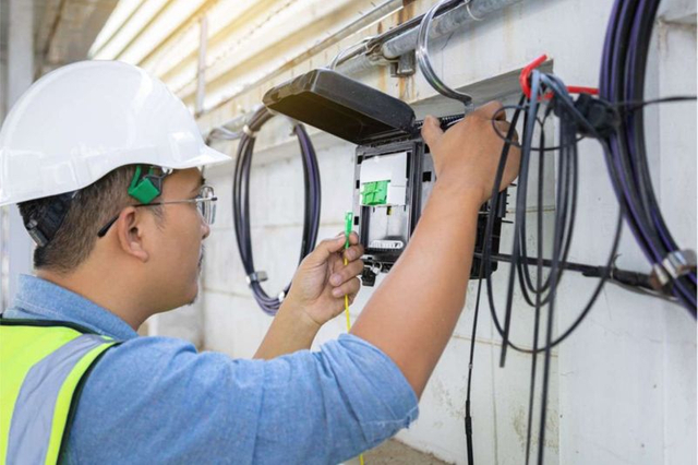
Identify the installed closure before counting spare space
Start with the asset record, installation drawing, enclosure markings and original bill of materials. Capture the manufacturer, model, variant, serial or batch reference where available, and any accessory changes made during earlier repairs. A housing that looks similar to a current catalog photograph may contain a different base, tray support or sealing arrangement.
Build a short evidence pack with external photographs, cable approach views and existing maintenance records. Open a working closure only under the operator’s approved work procedure. If the model cannot be established from records or visible markings, ask the manufacturer or responsible supplier to identify it before selecting replacement parts.
| Record | What to capture | Why it changes the decision |
|---|---|---|
| Closure identity | Model, variant, revision and installation history | Defines which accessory documentation applies. |
| Current cable population | Cable IDs, entry positions and jacket dimensions | Reveals occupied and potentially reusable positions. |
| Internal configuration | Installed tray types, holders and storage arrangements | Shows what is fitted, rather than the catalog maximum. |
| Condition | Seal condition, housing damage and previous water ingress | May require repair or replacement before expansion. |
| Site access | Mounting, available slack and safe working position | Determines whether re-entry can be carried out as planned. |
Do not treat a missing part number as a minor purchasing detail. Put it on the open-item list with an owner and a confirmation date. This prevents a speculative accessory order from becoming an installation-day problem.
Check each cable entry against the proposed cable
Create an entry map with a separate row for each position. Distinguish occupied entries, sealed spare entries, express or mid-span arrangements, and openings that are not approved cable positions. Record whether a proposed addition would require disturbing a seal shared with an existing cable.

The opening in the housing and the cable range accepted by its seal are different specifications. Measure the jacket where the seal will contact it, note whether the cable is round or flat, and identify the proposed sealing kit. For a kit accommodating several cables, confirm the permitted cable combination and the treatment of unused positions. Do not assume that several small cables can replace one larger cable in a seal.
Also check the path immediately outside and inside the entry. Cable approach, support and strength-member anchoring must allow the new cable to reach its intended tray without loading existing fibers. A position that is physically empty may be unusable because the neighboring cable or mounting bracket blocks access.
For background on enclosure geometry, the inline versus dome closure selection guide explains why entry layout matters. For expansion, take the next step: confirm the specific entry, cable and seal combination on the installed unit.
Build the sealing and re-entry parts list
Request a complete fiber closure sealing kit by part number and application. Identify which parts are supplied together and which must be ordered separately. The list may include entry seals, cable-size adapters, blanking components, a housing sealing ring, clamps or consumables, depending on the closure design. Do not substitute a generic gasket solely because its visible dimensions look close.
- Ask which components may be reused after opening, what condition checks apply, and which must be replaced. Use the instructions for the installed model and seal system.
- Confirm permitted preparation materials and tools. Cleaning agents, lubricants and sealing consumables should follow the specified procedure.
- Review the environmental requirement for the completed configuration. A housing rating alone does not establish the performance of a different cable and seal arrangement.
- Include unused-port closure parts and any components needed to return the original configuration to service if the expansion cannot proceed.
Use a parts reconciliation sheet with four states: installed and retained, installed and replaced, new addition, and contingency spare. This is more useful to a field crew than a single bag labeled accessories. Keep the matched kits together and identify them against the entry map.
For example, a newly ordered branch cable may need an entry kit, an anchoring component and routing accessories even when no additional tray is required. Conversely, an extra tray does not resolve a missing or unsuitable cable seal. Check the complete change rather than buying only its most visible part.
Verify tray compatibility and remaining working capacity
Splice tray compatibility includes more than outer dimensions. Confirm the tray mounting or hinge arrangement, stack limits, splice-holder type, supported protector format and route from the cable entry. A tray that fits inside the shell can still interfere with the cover, fiber routing or access to lower trays.

Count existing occupied splice positions, reserved positions and the new splices separately. Record the basis of the count: individual fibers, ribbon splices, adapter positions and splitter outputs are not interchangeable quantities. When a different splice format is proposed, verify the holder and organizer configuration instead of applying a capacity figure from another configuration.
Inspect whether there is a defined path for buffer tubes, fibers and slack as trays are accessed and returned to position. Keep the specified bend limits and protect existing circuits from movement. The maintenance question is not only whether the additional splices can be stored, but whether a technician can revisit them without pulling neighboring fibers out of their guides.
| Capacity check | Evidence needed | Do not infer from |
|---|---|---|
| Entry capacity | Approved cable and seal layout | Number of visible holes alone |
| Splice capacity | Installed compatible trays and holder arrangement | Maximum fiber count in a family brochure |
| Storage capacity | Routing plan for spare or uncut fibers and tubes | Empty volume inside the dome or shell |
| Service capacity | Tray movement and access review | The ability to close the lid once |
Plan the work package and acceptance evidence
Define the affected circuits and the work boundary before purchasing the final kit. Record the access window, responsible crew, network protection arrangements where applicable, and the point at which work must stop if an unexpected condition appears. Prepare the materials needed to secure and reseal the existing closure as well as the planned addition.
Separate a visual condition review from optical acceptance. Agree which existing and new fibers require baseline records and post-work measurements, the test boundaries, applicable limits and reporting identifiers. Use the operator’s procedure for any sealing verification. Do not invent a pressure test or test value where the closure instructions do not authorize it.
After the work, update the entry map, cable schedule, tray allocation and accessory record. File the accepted test results against the affected circuit IDs. Photograph the final condition where the operator allows it, including secured cables, closed unused positions and the restored mounting arrangement.
The fiber restoration planning guide provides a related preparation framework. An expansion work package should likewise account for the materials and records needed if the planned change encounters an unexpected field condition.
Convert the findings into an expansion RFQ
The RFQ should ask for a configuration review, not simply additional trays. Send the installed model information, entry map, cable dimensions, existing tray configuration and proposed splice allocation. Ask the supplier to mark any item that cannot be confirmed from the available evidence.
| RFQ line | Information to provide |
|---|---|
| Existing asset | Closure model, variant, photos, drawings and current parts list |
| Proposed cable addition | Cable construction, shape, measured jacket dimensions and entry assignment |
| Fiber work | New splice count, splice format, reserved capacity and existing services affected |
| Accessory request | Seals, trays, holders, anchoring, blanking and required re-entry materials |
| Acceptance | Required technical confirmation, instructions and project test records |
| Delivery | Quantity per closure, site grouping and required work window |
Close the review with one of three decisions: proceed with the confirmed kit; proceed after specified repairs or configuration changes; or redesign the joint arrangement. Keep unresolved compatibility items on hold. A replacement closure may be the practical answer when the installed unit cannot support the approved entry, organizer or maintenance arrangement.
Frequently asked questions
Does spare splice capacity mean an existing closure can be expanded?
No. Check usable cable entries, matching seals, installed tray compatibility, fiber storage and maintenance access as separate constraints. Any one of these can limit the proposed addition.
Can I use a tray from another closure if the dimensions match?
Matching dimensions are not enough. Confirm the mounting system, stack arrangement, splice holders, routing and approved compatibility with the installed closure variant.
What information is needed to quote an expansion kit?
Provide the closure identity, current entry and tray layout, proposed cable dimensions, splice requirements, environmental conditions and the parts or documentation already available.
Prepare a closure expansion request
Send the installed model details, cable-entry photos, cable dimensions, tray information and proposed splice allocation for a configuration and accessory review.



 Fiber Optic Cable
 Fiber Optic Tools
 Ethernet Cable
 Coaxial Cable
 Fire & Security Cable
 Voice, Audio & Video
 Power & Control Cable