Solutions for 4G Business - Optical Fiber Cable for Distributed Base Station
Author: Isaac Publish Time: 25-03-2025 Origin: Site
Hybrid Fiber-Power Cable for Distributed Base Stations
A hybrid fiber-power cable combines optical fibers for fronthaul or equipment communication with insulated copper conductors for remote DC power. It can reduce the number of separate cable runs between a centralized equipment location and remote radio equipment, but it does not replace the need for an engineered optical link, electrical power design, protection system, and compliant installation pathway.
The concept remains relevant to existing 4G BBU/RRU sites and to newer 4G/5G deployments using distributed units and radio units. The cable construction should be selected only after the radio architecture, optical interface, remote load, route, redundancy, and local safety requirements are confirmed.

■ Where Hybrid Cable Fits in 4G and 5G Radio Networks
In a traditional distributed 4G base station, the baseband unit is separated from remote radio units or remote radio heads located closer to the antennas. Optical fiber carries the digitized radio interface, while copper conductors supply power to the remote equipment. CPRI is widely associated with this BBU-to-RRU architecture and supports optical physical interfaces for remote radio equipment.
Newer networks may use eCPRI or an O-RAN open fronthaul interface between distributed and radio units. These packet-based or lower-layer split architectures can change bandwidth, timing, synchronization, transceiver, and network requirements, but they still need a physical optical path and a suitable method of powering the remote radio equipment.
Selection rule: Specify the radio interface and equipment ports first. A cable described as “4G,” “5G,” “RRU,” or “FTTA” is not automatically compatible with the required optical protocol, connector, fiber type, power load, or environmental route.
■ How Remote DC Power Works
A remote power system normally includes a central power source, protection and monitoring, copper conductors within the hybrid cable, and a remote power interface or converter at the radio location. Some systems distribute the equipment’s normal DC supply directly over a limited distance. Other engineered systems use a higher distribution voltage to reduce current and voltage drop, then convert it to the required equipment voltage at the remote end.
Higher-voltage remote feeding is not a generic cable feature. It requires compatible source and remote equipment, overcurrent and fault protection, isolation, disconnecting means, monitoring, surge protection, earthing or bonding as applicable, warning labels, and controlled access. The final design must follow the network operator’s rules and the electrical and telecommunications regulations for the installation location.
Conductor size is selected from the remote load, starting and peak current, route length, allowable voltage drop, cable resistance at operating temperature, redundancy plan, and permitted cable temperature. Optical fibers do not carry electrical power; the metallic conductors in the hybrid cable are dedicated to the power-feeding circuit unless the product specification explicitly defines another function.
■ Common Distribution Topologies
Point-to-point
A dedicated hybrid cable connects one central location to one remote equipment point. This is often the simplest arrangement for calculating optical loss, conductor voltage drop, protection, fault isolation, and spare capacity. Multiple radio units may be grouped at the remote point only when the power and fiber design supports their combined demand.

Point-to-multipoint
A feeder route serves several remote points through planned distribution or branching locations. This can suit indoor coverage systems, campuses, transport facilities, or dense small-cell areas. Each branch needs its own optical allocation, power budget, protection, connector or splice plan, and failure-isolation method. Branching the fiber and branching the power circuit are separate engineering decisions.

Linear or cascade route
Remote sites are arranged along one direction, such as a highway, railway, tunnel, or pipeline corridor. The design must account for cumulative route length, fiber allocation, splice loss, voltage drop to each node, sectional protection, isolation, and the operational impact of a feeder fault. Ring or redundant routing may be preferable when service availability is critical.

■ Choose the Cable Construction for the Route
Aerial and pole routes
Aerial routes require a verified span design, tensile rating, sag and wind calculation, UV-resistant jacket, compatible suspension or tension hardware, and clearance from power systems. A self-supporting construction such as the GDTC8S figure-8 hybrid optical and electrical cable is one construction to evaluate when the project calls for a messenger-supported aerial route.
Duct and direct-burial routes
Underground routes may require water blocking, crush and impact resistance, pulling-tension control, rodent protection, corrosion assessment, and armor bonding. Direct-burial suitability must be stated for the exact cable. The GDTA53 double-sheath APL/PSP armored hybrid cable is a product example for projects evaluating a double-sheath, dual-metallic-layer construction; its current datasheet should decide the permitted installation method.
Indoor and equipment-area transitions
Where the route enters a building or occupied technical space, the cable and transition point must meet the applicable flame, smoke, halogen, pathway, and grounding requirements. The GDFJAH APL-armored LSZH hybrid cable illustrates a sub-unit and electrical-conductor construction to compare for routes requiring an LSZH sheath. LSZH does not by itself prove outdoor, fire-resistance, or regulatory compliance.
■ Optical Link Requirements
Fiber type: Match the radio and baseband or DU transceivers. Single-mode G.652 or bend-insensitive G.657 fibers are common choices, while multimode is used only when the equipment and distance require it.
Fiber count: Include working fibers, redundancy, monitoring needs, future radios, and practical spares rather than sizing only for the first installation.
Optical budget: Calculate fiber attenuation, connector loss, splice loss, splitters or multiplexers, engineering margin, transmitter power, and receiver sensitivity.
Interfaces: Confirm wavelength, data rate, transceiver form factor, connector type, polarity, timing, and synchronization requirements.
Acceptance: Define inspection, polarity verification, insertion-loss testing, OTDR testing where appropriate, and the required handover records.
■ Electrical and Protection Requirements
Remote load: Use the equipment manufacturer’s normal, peak, and startup power requirements, including heaters, fans, and future radio expansion.
Conductor design: Calculate loop resistance, voltage drop, power loss, temperature rise, conductor grouping, and terminal compatibility.
Fault protection: Define overcurrent protection, short-circuit behavior, insulation monitoring where required, isolation, shutdown, and restart controls.
Surge and lightning protection: Coordinate surge-protective devices, cable shields or armor, bonding, earthing, and equipment protection. An enclosure alone cannot provide complete lightning protection.
Availability: Decide whether the site needs dual feeds, separate routes, backup energy, remote alarms, branch isolation, or monitored power conversion.
■ Mechanical and Environmental Requirements
Cable construction must match the complete route rather than only the radio equipment. Confirm maximum pulling tension, minimum bend radius during installation and operation, crush and impact resistance, cable weight, support spacing, water-blocking method, UV exposure, operating and installation temperatures, chemicals, salt, rodents, vibration, and expected service life.
Armor, LSZH sheaths, PE sheaths, water blocking, and double jackets solve different problems. None of these terms alone proves that a cable is suitable for aerial spans, direct burial, indoor fire zones, or a particular electrical safety regime.
■ Project Information Needed for Cable Selection
Prepare the following information before requesting a hybrid cable design or quotation:
4G/5G architecture, radio model, central equipment, interface, data rate, wavelength, and transceiver type.
Topology, route drawing, link lengths, branch locations, splice points, redundancy, and spare-fiber policy.
Remote equipment voltage, normal and peak power, permitted voltage range, backup requirement, and protection philosophy.
Aerial, duct, tray, tunnel, building, or direct-burial pathway, including spans, pulling conditions, and transition points.
Temperature, UV, water, salt, chemicals, rodents, vibration, lightning exposure, and applicable fire or smoke requirements.
Required cable standards, national regulations, operator specifications, test reports, drum lengths, labeling, and delivery documentation.
■ Frequently Asked Questions
Is a hybrid fiber-power cable only for 4G networks?
No. Hybrid cables can support existing 4G BBU/RRU systems and newer architectures when the optical interface, remote power design, cable construction, and equipment connections are compatible. The cable must be specified for the actual network rather than selected only by generation label.
Can one hybrid cable feed several radio units?
It can when the fiber count, conductor capacity, branch design, protection, voltage drop, fault isolation, and total remote load have been engineered for all connected units. A multipoint diagram alone does not confirm electrical capacity.
Should the cable use single-mode or multimode fiber?
Use the fiber specified by the radio, baseband or distributed unit, transceiver, wavelength, reach, and optical budget. Single-mode fiber is common in outdoor mobile networks, but it should not be assumed without checking the equipment interface.
Does armor make a hybrid cable suitable for direct burial?
Not automatically. Armor provides a defined type of mechanical protection, while direct burial may also require verified water blocking, sheath construction, crush resistance, corrosion protection, installation limits, and compliance with the project specification. Confirm the exact product datasheet.



 Fiber Optic Tools
Products 6 families
Solutions 6 markets
Resources Tools & docs
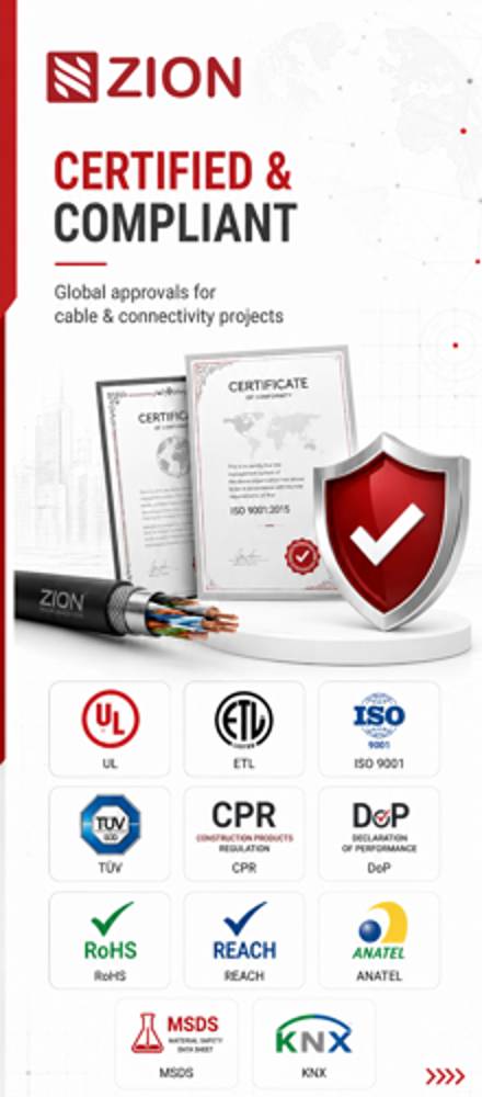
Certificate
Certification and compliance references for project review, qualification and purchasing documentation.
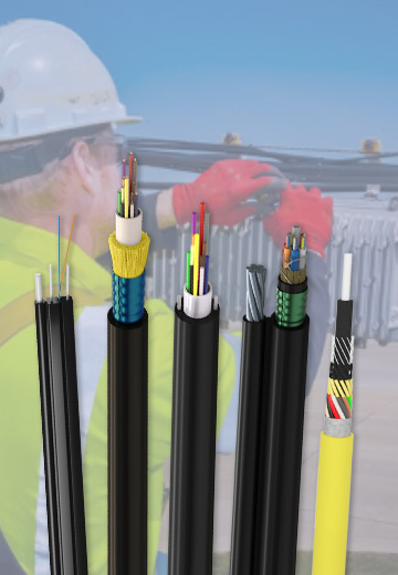 Fiber Optic CableAccess and backbone
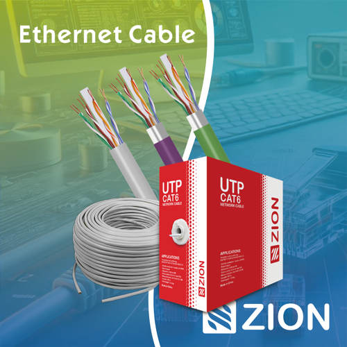 Ethernet CableCat5e to Cat8
 Coaxial CableRF and video signal
 Fire, Security & AlarmSafety systems
 Voice, Audio & VideoSignal cabling
 Power & Control CableEnergy and control
Fiber optic cable systems
Outdoor, indoor, FTTH and distribution cable lines for access networks, backbone routes and campus deployments.
 Telecom & ISP NetworksFTTH, PON, ODN
 Data Center InfrastructureServer room cabling
 Building Low-Voltage SystemsBMS, AV, weak current
 Security & Fire ProtectionAlarm, CCTV, access
 Industrial Automation CablePLC, RS485, fieldbus
 Energy & Power InfrastructureSolar, battery, power
Telecom & ISP Networks
For FTTH / PON access, outdoor fiber deployment, aerial routes, duct routes, direct burial routes, rural broadband and ODN planning.
Tools
Use calculators and planning tools for conduit capacity, PoE voltage drop and fiber optic link loss budget work.