Twisted Pair Network Cables: Cat5e to Cat8
Author: Site Editor Publish Time: 07-07-2021 Origin: Site
Four-pair twisted copper cable is the standard medium behind many Ethernet links in offices, data rooms, industrial facilities, and security systems. Understanding component category, channel performance, shielding, conductor, jacket, link length, and test limits makes cable selection more reliable.
What Is a Twisted Pair Network Cable?
A twisted pair network cable carries data as balanced differential signals over pairs of insulated copper conductors. The conductors in each pair are twisted together so that external noise tends to affect both wires similarly. The receiver responds to the difference between the conductors and rejects much of the common-mode noise.
This guide covers the familiar four-pair balanced cabling used for premises Ethernet, not single-pair Ethernet. Pair geometry, twist rate, conductor size, insulation, separators, shielding, and the outer jacket all influence transmission performance. The category name—such as Cat 5e, Cat 6, Cat 6A, or Category 8—describes a standards-based component performance level; it does not, by itself, define the jacket rating, conductor construction, shield design, or suitability for every environment.
Twisted pair cabling can be used in permanent links inside walls and pathways, as flexible patch cords in racks and work areas, or as part of pre-terminated copper assemblies. The full channel includes the cable, connectors, patch panels, outlets, and patch cords, so end-to-end performance depends on more than the bulk cable alone.

Each pair carries equal and opposite signals, helping the receiver reject common-mode noise.
Different pair twist rates help limit crosstalk between the four pairs inside the cable.
Cable, connectors, patching, installation quality, and length must work together as one channel.
Twisted Pair Cable Categories: Cat5e to Cat8
Category selection should start with the required Ethernet application and maximum channel length. In standards language, category normally describes cable and connecting-hardware components, while class describes the performance of an installed ISO/IEC link or channel. The values below are planning references; the governing project standard, application standard, component data, and field-test limit remain the final authority.
| Category | Rated frequency | Typical Ethernet planning | Common project use | Standards context |
|---|---|---|---|---|
| Cat 5e | 100 MHz | 1GBASE-T to 100 m; 2.5G/5G may be supported when the installed cabling is qualified | General LAN, access points, cameras, building systems | ANSI/TIA Category 5e; ISO/IEC Category 5e / Class D |
| Cat 6 | 250 MHz | 1G/2.5G/5G to 100 m; 10GBASE-T only over qualified reduced-length channels | Enterprise LAN, PoE devices, qualified shorter 10G links | ANSI/TIA Category 6; ISO/IEC Category 6 / Class E |
| Cat 6A | 500 MHz | 10GBASE-T up to a 100 m channel | 10G structured cabling, dense pathways, data rooms | ANSI/TIA Category 6A; ISO/IEC Category 6A / Class EA |
| ISO/IEC Category 7 | 600 MHz | Class F channels can support 10GBASE-T to 100 m | Shielded Class F systems with matching connectivity | ISO/IEC Category 7 components / Class F cabling; not an ANSI/TIA category |
| ISO/IEC Category 7A | 1,000 MHz | Class FA channels can support 10GBASE-T to 100 m | Shielded Class FA systems with matching connectivity | ISO/IEC Category 7A components / Class FA cabling; not an ANSI/TIA category |
| Category 8 | 2,000 MHz | 25GBASE-T or 40GBASE-T up to a 30 m channel: typically 24 m permanent link plus 6 m of cords | Standardized short data-center links where compatible BASE-T equipment is specified | ANSI/TIA Category 8; ISO/IEC Category 8.1/Class I or Category 8.2/Class II |
Rated frequency is not the same as Ethernet data rate. Cat 6 does not have a blanket “10 Gbps at 55 m” guarantee: support depends on channel length, topology and alien-crosstalk performance, and installed Cat 6 should be assessed for 10GBASE-T. A cable marked Category 7 or 7A and terminated with ordinary Category 6A RJ45 hardware is not automatically a Class F or FA channel. Category 8 is a specialized short-reach option; active-equipment support and comparison with DAC or fiber should be confirmed before specifying it.

How to Read U/UTP, F/UTP, U/FTP, and S/FTP
The ISO/IEC naming format separates the overall cable shield from the shield around individual pairs. The letters before the slash describe the overall shield; the letters after the slash describe the pair shield.
| Designation | Overall shield | Pair shield | Practical meaning |
|---|---|---|---|
| U/UTP | None | None | Light, flexible, and simple to terminate; common in controlled commercial pathways. |
| F/UTP | Foil | None | One overall foil adds external noise protection without shielding each pair. |
| U/FTP | None | Foil | Individual pair foil helps control pair-to-pair coupling and alien crosstalk. |
| F/FTP | Foil | Foil | Overall foil plus individually foiled pairs. |
| S/FTP | Braid | Foil | Overall braid plus individually foiled pairs for demanding EMI environments. |
| SF/UTP | Braid and foil | None | Dual overall shielding around unshielded pairs. |
Shielding is not automatically the right answer for every pathway. A screened channel should use compatible screened connecting hardware, maintain screen continuity, and follow the building telecommunications bonding and earthing design. The screen is part of a system-level EMC strategy, not a substitute for pathway separation or correct installation. U/UTP remains a practical option where electromagnetic exposure is controlled and separation from power and noise sources is properly managed.


How to Choose the Right Twisted Pair Cable
A useful cable specification connects network performance to the physical route. Selecting the highest category without checking the pathway, shield termination, PoE load, connector system, and jacket requirement can increase cost without solving the real project risk.
Define the Ethernet application and the complete channel length, including patch cords.
Review motors, drives, power cables, radio equipment, tray separation, and bonding provisions.
Confirm indoor, outdoor, conduit, riser, plenum, LSZH, UV, moisture, and mechanical requirements.
Use standards-compliant annealed copper conductors; choose solid cable for permanent links and stranded cords for flexible patching, then assess resistance unbalance and bundle heating for PoE.
Match cable category and shielding with jacks, plugs, patch panels, cords, and termination tools.
State whether the project requires component data, permanent-link certification, or channel certification.
For a purchase specification, also define conductor material, AWG, maximum cable diameter, jacket material and rating, reel or pull-box length, print legend, applicable standards, and required reports. The ZION LAN and Ethernet cable range provides category and construction options for structured cabling projects.
How Twisted Pair Cable Is Manufactured
Manufacturing consistency is essential because small changes in conductor diameter, insulation concentricity, pair lay, and jacket geometry can change impedance, attenuation, return loss, and crosstalk. A simplified production flow is:
Draw and anneal the copper conductor; strand conductors where a flexible cord design requires it.
Extrude insulation and control wall thickness and concentricity.
Twist insulated conductors into pairs using controlled lay lengths.
Cable the pairs together and add separators or shields where specified.
Extrude, print, cool, inspect, test, and package the outer jacket.

Material and fire-performance requirements vary by market and installation location. These references have different roles: UL 444 is a communications-cable product standard, UL 1581 contains wire and cable test methods, UL 1666 addresses flame propagation for riser cables, IEC 60332 covers specified vertical flame tests, and EN 50399 is used for reaction-to-fire testing under the European CPR framework. A data category does not establish a fire rating, so the required classification must be verified for the exact cable and route.
Testing and Certification: Cable, Permanent Link, and Channel
Test terminology matters. A component test evaluates cable or connecting hardware against component limits. A permanent-link test normally covers the installed fixed cable and the connecting hardware at both ends but excludes equipment and work-area cords. A channel test adds the cords used to connect equipment. The familiar 100 m model applies to Classes D through FA; Category 8/Class I or II uses a maximum 30 m channel.
Field certification can include wire map, length, propagation delay, delay skew, DC loop resistance, resistance unbalance, insertion loss, return loss, NEXT, power-sum NEXT, ACR-F and power-sum ACR-F. The selected standard and test limit determine which parameters are pass/fail requirements. Cat 6A/Class EA acceptance may also require an alien-crosstalk strategy, particularly for dense unshielded installations. A vector network analyzer with suitable fixtures is used for laboratory component characterization; it is not the same tool or test method as a field channel certifier.
Instrument capability must match the limit. Fluke Networks specifies the DSX2-5000 for testing up to Category 6A/Class FA at 1 GHz, while the DSX2-8000 supports Category 8/Class I and II limits to 2 GHz. The DTX-1800 shown in many older cabling articles is a discontinued legacy platform and should not be presented as a current Category 8 certification solution.

A passing report is most useful when it identifies the cable ID, test standard, limit, adapter type, calibration status, measured result, and test date. Visual inspection, correct bend radius, pair-twist preservation at terminations, shield continuity, labeling, and pathway workmanship remain important even when the electrical test passes.
Standards references for project documents
ANSI/TIA-568.2-E for balanced twisted-pair cabling and components.
ISO/IEC 11801-1 and the applicable part of the ISO/IEC 11801 series for generic customer-premises cabling.
IEEE 802.3 application requirements for the Ethernet PHY being deployed, together with the selected TIA or ISO/IEC cabling test limit.
The current instrument manufacturer documentation for supported category, class, frequency, adapters, software and calibration status.
Twisted Pair Network Cable FAQ



 Fiber Optic Tools
Products 6 families
Solutions 6 markets
Resources Tools & docs
Certificate
Certification and compliance references for project review, qualification and purchasing documentation.
 Fiber Optic CableAccess and backbone
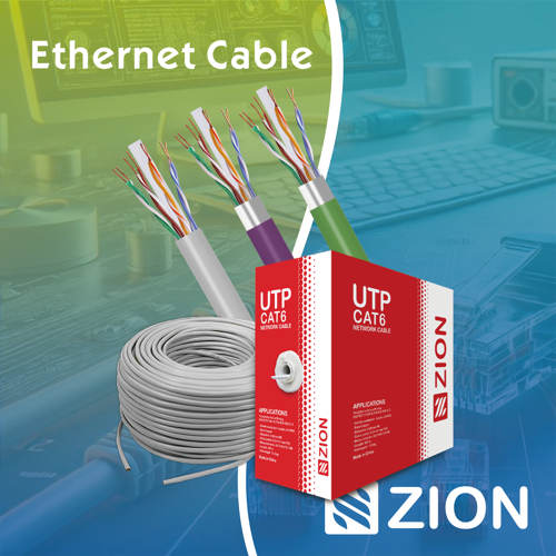 Ethernet CableCat5e to Cat8
 Coaxial CableRF and video signal
 Fire, Security & AlarmSafety systems
 Voice, Audio & VideoSignal cabling
 Power & Control CableEnergy and control
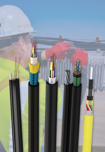
Fiber optic cable systems
Outdoor, indoor, FTTH and distribution cable lines for access networks, backbone routes and campus deployments.
 Telecom & ISP NetworksFTTH, PON, ODN
 Data Center InfrastructureServer room cabling
 Building Low-Voltage SystemsBMS, AV, weak current
 Security & Fire ProtectionAlarm, CCTV, access
 Industrial Automation CablePLC, RS485, fieldbus
 Energy & Power InfrastructureSolar, battery, power
Telecom & ISP Networks
For FTTH / PON access, outdoor fiber deployment, aerial routes, duct routes, direct burial routes, rural broadband and ODN planning.
Tools
Use calculators and planning tools for conduit capacity, PoE voltage drop and fiber optic link loss budget work.