MPO-LC Harness Cables for High-Density Fiber Breakout
MPO-LC harness cables are pre-terminated assemblies that convert one high-density MPO or MTP interface into multiple LC duplex connections. ZION supplies 8F, 12F and 24F configurations in OM3, OM4 and OS2 fiber. Start by matching the breakout architecture, then confirm polarity, MPO gender, connector polish, loss grade, jacket and leg structure.
MPO-LC Harness Cable Product Range
This product family covers MPO or MTP backbone interfaces breaking out to LC duplex connections. The assembly can be configured by fiber count, fiber type, polarity, gender, endface, jacket, length and loss grade, so the ordering code should follow the complete channel design rather than the connector name alone.
![ZION MPO-LC harness cable with MPO or MTP to LC duplex breakout]()
MPO FIBER OPTIC CABLE
MPO/MTP to LC Harness Cable
Choose this assembly for a factory-terminated transition from an MPO/MTP backbone to 4, 6 or 12 LC duplex connections. Available configurations include 8F, 12F or 24F and OM3, OM4 or OS2. Confirm polarity, MPO gender, loss grade and breakout-leg construction for the selected version.
View Product Details → How Do I Choose an MPO-LC Harness Cable?
Choose the architecture first, then verify the interface details. A connector that physically mates can still fail the channel when fiber count, lane mapping, polarity or gender is wrong.
How many fibers?
Use 8F for 4 × LC duplex breakout, 12F for 6 × LC duplex and 24F for 12 × LC duplex. Match the count to the transceiver lanes, panel design and port plan; unused or misassigned fibers can create a topology mismatch.
OM3, OM4 or OS2?
Select OM3 or OM4 for a multimode system and OS2 for a singlemode system. Distance depends on the complete optical standard, transceivers and link budget, so do not choose fiber type from cable color or connector shape alone.
Which polarity?
Specify Type A, Type B or Type C according to the end-to-end polarity plan. Polarity defines how transmit and receive fibers are mapped; the wrong method can prevent the link from working even when every connector fits.
Male or female MPO?
Match the pinned or unpinned connector to the transceiver, adapter or cassette interface. Confirm key orientation and mating hardware together with gender; forcing an incorrect pair can damage the connector.
Standard or low loss?
Use the project link budget to choose the loss grade. ZION lists MPO/MTP insertion loss of ≤0.75 dB for standard loss and ≤0.35 dB for low loss, with LC insertion loss of ≤0.30 dB; confirm the acceptance limit on the quotation and test report.
Quick Comparison of MPO-LC Harness Configurations
The fiber count determines the LC breakout ratio; fiber type and interface details determine whether the assembly fits the system. Treat the examples below as configuration paths, then confirm the complete drawing and link budget before ordering.
| Configuration | LC Breakout | Fiber Options | Typical Fit | Confirm Before RFQ |
|---|
| 8F MPO/MTP-LC Harness | 4 × LC duplex | OM3 / OM4 / OS2 | 40G to 4 × 10G breakout or compact equipment links | Transceiver lane map, polarity and gender |
| 12F MPO/MTP-LC Harness | 6 × LC duplex | OM3 / OM4 / OS2 | General backbone-to-port distribution | Port plan, polarity, LC numbering and leg length |
| 24F MPO/MTP-LC Harness | 12 × LC duplex | OM3 / OM4 / OS2 | High-density distribution zones | Panel space, labeling, routing and cable management |
| Low-Loss MPO/MTP-LC Harness | 4, 6 or 12 × LC duplex | OM3 / OM4 / OS2 | Channels with a tighter optical loss budget | Specified maximum insertion loss and test report |
Which Technical Specifications Affect the Link?
Insertion loss, return loss, temperature range and mechanical strength affect the link budget and installation reliability. Apply the values to the selected fiber type and loss grade, and request the corresponding test criteria in the purchase specification.
| Specification | Singlemode | Multimode | Why It Matters |
|---|
| MPO/MTP insertion loss | Standard ≤0.75 dB / Low loss ≤0.35 dB | Standard ≤0.60 dB / Low loss ≤0.35 dB | Controls available channel margin |
| LC insertion loss | ≤0.30 dB | ≤0.30 dB | Adds to total channel attenuation |
| Return loss | MPO ≥60 dB / LC UPC ≥50 dB / LC APC ≥60 dB | MPO ≥25 dB / LC ≥35 dB | Indicates reflection performance |
| Durability | 200 mating cycles typical | 200 mating cycles typical | Supports planned maintenance cycles |
| Operating temperature | -40°C to +85°C | -40°C to +85°C | Defines the stated environmental range |
| Tensile strength | >70 N | >70 N | Helps protect the assembly during routing |
Performance values must be confirmed for the exact connector system, fiber type, polish and loss grade ordered. Do not combine values from different versions when calculating the channel budget.
Where Do MPO-LC Harness Cables Fit?
These assemblies fit projects that need a predictable, factory-terminated transition from high-density parallel fiber to LC equipment ports. They are not a substitute for confirming the transceiver standard, complete channel polarity or optical budget.
40G to 4 × 10G breakout
An 8F assembly can provide four LC duplex paths for a compatible breakout design. Confirm the QSFP lane mapping, polarity and transceiver support before specifying the cable.
Data center distribution
Use 12F or 24F configurations when port density and organized routing are priorities. Check available panel space, bend management, breakout-leg protection and labeling before choosing the layout.
Panel-to-equipment links
Labeled LC legs can simplify identification between a patch panel and active equipment. Confirm leg numbering, equal or staggered lengths and protection during routing.
Modular cassette systems
A low-loss MTP/MPO-LC configuration may suit a modular system with several connection points. Verify male/female interfaces and every component in the mating ecosystem; do not assume all cassettes use the same pinning or polarity.
Frequently Asked Questions
What is an MPO-LC harness cable?
It is a pre-terminated fiber assembly with one MPO or MTP connector on one side and multiple LC connections on the other. It converts a high-density backbone interface into equipment-ready LC duplex links without field termination.
What is the difference between 8F, 12F and 24F harness cables?
The main difference is the number of fibers and LC duplex breakouts: 8F provides 4, 12F provides 6 and 24F provides 12. The correct choice depends on the port plan and lane architecture, not simply on the highest available fiber count.
Can an MPO-LC harness cable be used for 40G to 10G breakout?
Yes, an 8F MPO/MTP-to-4 × LC duplex assembly can fit a compatible 40G-to-4 × 10G breakout design. Confirm that both transceivers support breakout operation and that the lane map, polarity and fiber type match.
Is MTP the same as MPO?
MTP is a specific multi-fiber connector product within the wider MPO interface family. Treat MPO and MTP as separate ordering choices and confirm the exact connector system, gender, key orientation and performance grade.
When should I choose a low-loss harness?
Choose low loss when the calculated channel budget needs additional margin or the path contains several mated connections. Use the complete link calculation and specify the maximum insertion loss rather than relying on the words “low loss” alone.
RFQ Checklist
You do not need to build a full part number before asking for a quote. Share the equipment and link plan plus the items below so the connector drawing, fiber map and test limits can be confirmed.
Application, equipment models and transceiver standards
Fiber count: 8F, 12F or 24F
Fiber type: OM3, OM4 or OS2
MPO or MTP connector, male or female, and key orientation
Polarity: Type A, Type B or Type C, with the required fiber map
LC endface: UPC or APC
Overall cable length, breakout-leg length, leg diameter and equal or staggered layout
Jacket requirement: LSZH, OFNR or OFNP
Standard-loss or low-loss limit and required test report
Quantity, labeling, serial control and packaging requirements





 Fiber Optic Cable
 Fiber Optic Tools
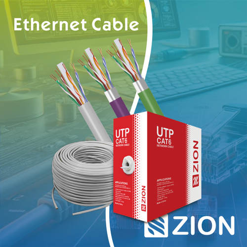 Ethernet Cable
 Coaxial Cable
 Fire & Security Cable
 Voice, Audio & Video
 Power & Control Cable