D-FB Coax Cable: 50 Ohm RF Feeder Series
D-FB coax cable is a 50 ohm RF cable family for wireless communication, antenna feeder, base station, paging, and equipment-room links. The range covers nine products from 3D-FB to 12D-FB, including bare-copper and copper-clad-aluminum conductor options. Start by matching cable size and conductor material to the route length, operating frequency, installation space, connector, and loss budget.
Which D-FB coax cable models are available?
The series includes compact 3D-FB and 5D-FB cables, mid-size 7D-FB and 8D-FB cables, and larger 10D-FB and 12D-FB feeder options. Bare copper (BC) is available throughout the listed range, while copper-clad aluminum (CCA) versions are listed for 8D-FB, 10D-FB, and 12D-FB. Confirm frequency-specific attenuation and connector compatibility for the selected code.
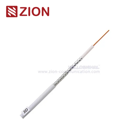
![NO.7101401 3D-FB bare copper 50 ohm coax cable]()
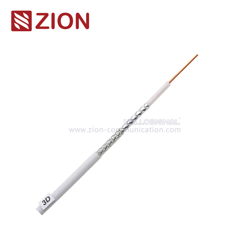
NO.7101401 3D-FB BC TC PE
50 ohm · 1.07 mm bare copper conductor · 5.40 mm PE jacket
Consider this compact model when routing space is limited. Confirm the required loss at the operating frequency and a 27 mm cable bend radius for the planned route.
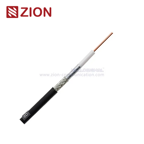
View 3D-FB details →![NO.7101403 5D-FB bare copper 50 ohm coax cable]()
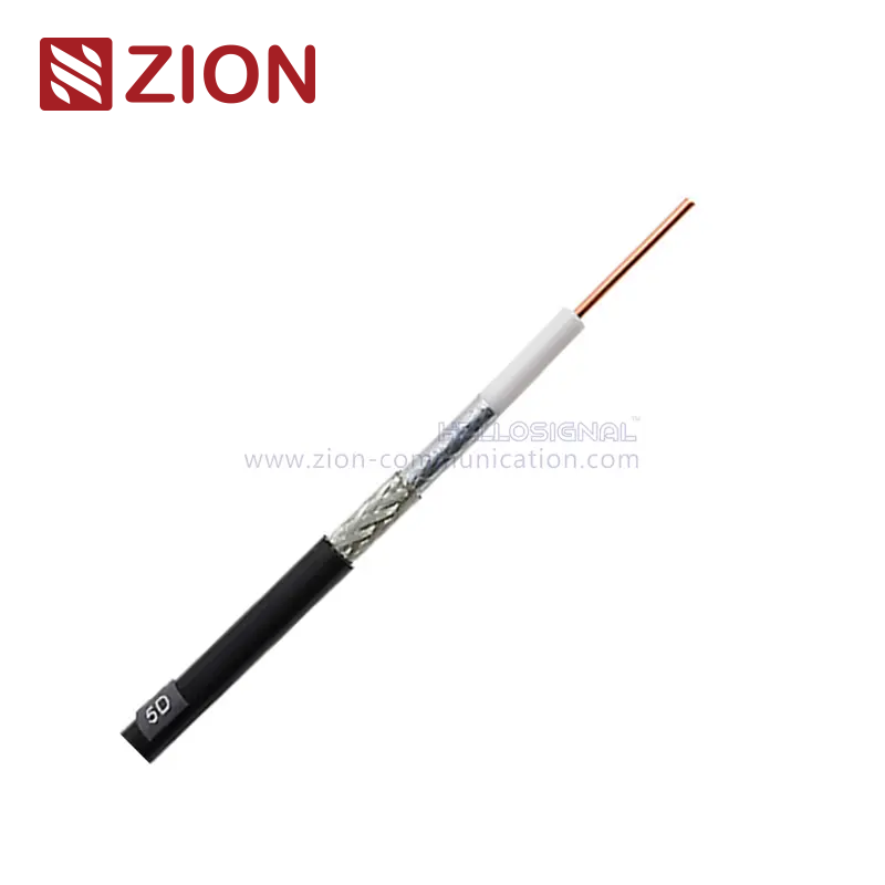
NO.7101403 5D-FB BC TC PE
50 ohm · 1.80 mm bare copper conductor · 7.50 mm PE jacket
Use 5D-FB as a mid-compact starting point when 3D-FB is too small for the loss target but the route still favors manageable cable size.
View 5D-FB details →![NO.7101405 7D-FB bare copper 50 ohm coax cable]()
NO.7101405 7D-FB BC TC PE
50 ohm · 2.60 mm bare copper conductor · 10.30 mm PE jacket
Consider 7D-FB when the route can accept a roughly 10 mm cable and the project needs a larger conductor than the 3D-FB or 5D-FB options.
View 7D-FB details →![NO.7101408 8D-FB bare copper 50 ohm coax cable]()
NO.7101408 8D-FB BC TC PE
50 ohm · 2.80 mm bare copper conductor · 11.10 mm PE jacket
Choose this 8D-FB version when the specified conductor must be bare copper. Check the connector, bend allowance, and attenuation table for the operating band.
View 8D-FB BC details →![NO.7101408e 8D-FB copper clad aluminum 50 ohm coax cable]()
NO.7101408e 8D-FB CCA TC PE
50 ohm · 2.80 mm CCA conductor · 11.10 mm PE jacket
Select this code only when copper-clad aluminum is acceptable in the project specification. Request its electrical data for a direct comparison with the BC version.
View 8D-FB CCA details →![NO.7101411 10D-FB bare copper 50 ohm coax cable]()
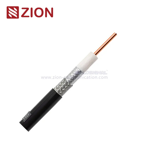
NO.7101411 10D-FB BC TC PE
50 ohm · 3.50 mm bare copper conductor · 13.00 mm PE jacket
Consider the BC 10D-FB code for feeder routes that can accommodate a 13 mm cable and require a larger bare-copper conductor.
View 10D-FB BC details →![NO.7101417 10D-FB copper clad aluminum 50 ohm coax cable]()
NO.7101417 10D-FB CCA TC PE
50 ohm · 3.50 mm CCA conductor · 13.00 mm PE jacket
This is the 10D-FB CCA alternative. Use the exact code in the RFQ and compare its DCR and attenuation with the BC product before approval.
View 10D-FB CCA details →![NO.7101414 12D-FB bare copper 50 ohm coax cable]()
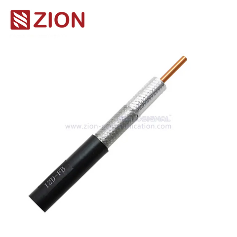
NO.7101414 12D-FB BC TC PE
50 ohm · 4.40 mm bare copper conductor · 15.60 mm PE jacket
This is the largest listed bare-copper option. Allow for the 15.60 mm jacket, routing support, bend management, and matching connector hardware.
View 12D-FB BC details →![NO.7101414e 12D-FB copper clad aluminum 50 ohm coax cable]()
NO.7101414e 12D-FB CCA TC PE
50 ohm · 4.40 mm CCA conductor · 15.60 mm PE jacket
Choose this code when the project accepts CCA in the largest listed D-FB size. Confirm electrical limits and connector termination against the final datasheet.
View 12D-FB CCA details →How do I choose a D-FB cable size?
Choose from the electrical requirement first, then confirm the cable can be installed and terminated correctly. The model number alone is not a complete loss specification, so use the final frequency, length, connector pair, and system loss budget when comparing sizes.
What is the loss budget?
Start with maximum allowable cable loss at the operating frequency and route length. Larger D-FB sizes are the usual shortlist for longer feeder runs, but the selected product's attenuation table must decide the final model.
How much route space is available?
Check jacket diameter, bend radius, tray or conduit space, support spacing, and service access. The listed jacket diameter rises from 5.40 mm for 3D-FB to 15.60 mm for 12D-FB, so a loss upgrade also changes installation requirements.
Bare copper or CCA?
Treat conductor material as a specification choice, not a name-only substitute. For 8D-FB, 10D-FB, and 12D-FB, compare the BC and CCA versions by DCR, attenuation, connector termination, project standard, and approved bill of materials.
Which connector is required?
Match the connector to the exact cable code and jacket dimensions. Confirm connector series, gender, orientation, installation method, and whether the order is bulk cable or a finished cable assembly.
One size for every route?
Usually, mixed routes should be evaluated by zone. Compact cable may suit short equipment-room links, while longer feeder sections may justify a larger size. This avoids paying the material and labor penalty of oversizing every run.
Quick comparison of D-FB models
Use conductor material and jacket diameter to narrow the physical options, then compare the frequency-specific electrical data for the exact product code. BC means bare copper; CCA means copper-clad aluminum.
| Product | Code | Inner Conductor | Jacket OD | Selection Starting Point |
|---|
| 3D-FB BC | 7101401 | 1.07 mm bare copper | 5.40 mm | Compact routing and short-link shortlist |
| 5D-FB BC | 7101403 | 1.80 mm bare copper | 7.50 mm | Mid-compact route with a larger conductor |
| 7D-FB BC | 7101405 | 2.60 mm bare copper | 10.30 mm | Larger-conductor feeder shortlist |
| 8D-FB BC | 7101408 | 2.80 mm bare copper | 11.10 mm | 8D size where BC is specified |
| 8D-FB CCA | 7101408e | 2.80 mm CCA | 11.10 mm | 8D size where CCA is approved |
| 10D-FB BC | 7101411 | 3.50 mm bare copper | 13.00 mm | Larger bare-copper feeder routes |
| 10D-FB CCA | 7101417 | 3.50 mm CCA | 13.00 mm | 10D size where CCA is approved |
| 12D-FB BC | 7101414 | 4.40 mm bare copper | 15.60 mm | Largest listed BC feeder option |
| 12D-FB CCA | 7101414e | 4.40 mm CCA | 15.60 mm | Largest listed CCA option |
What is inside a D-FB coax cable?
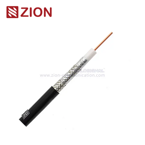
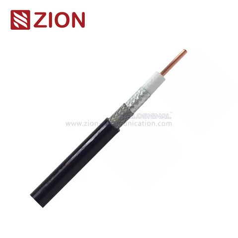
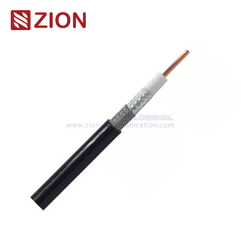
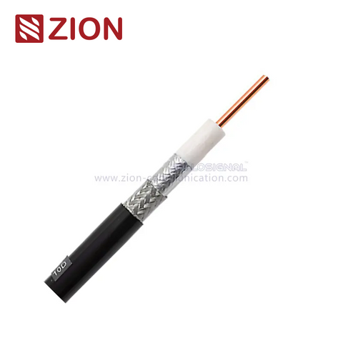
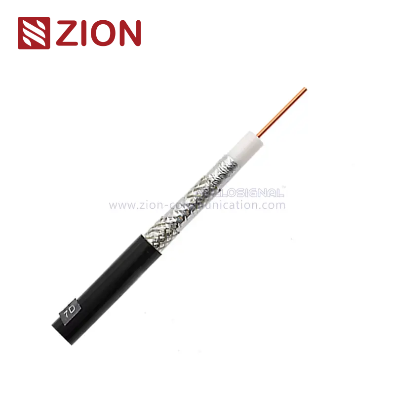
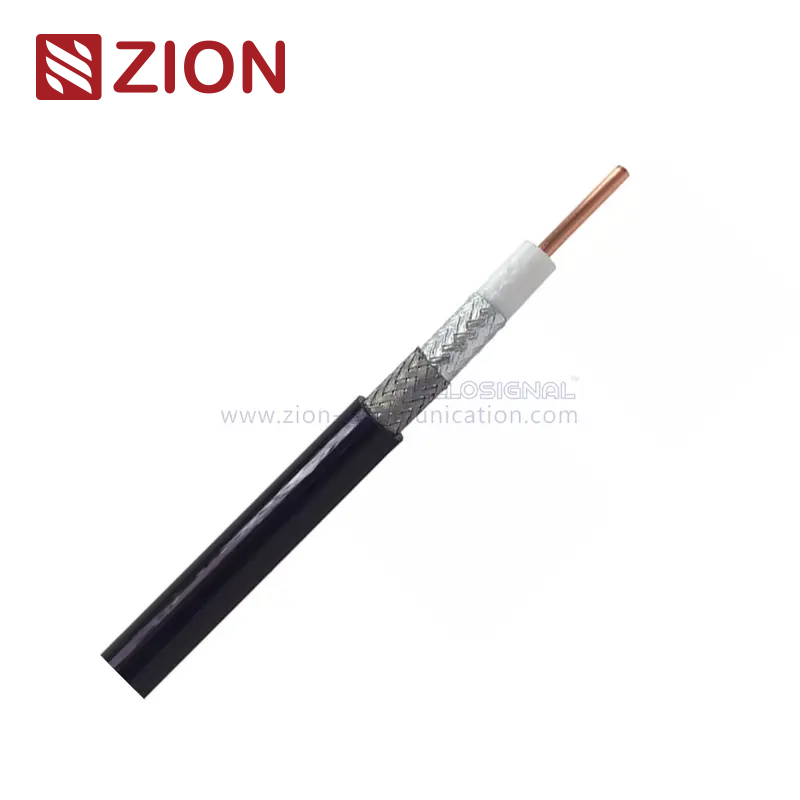
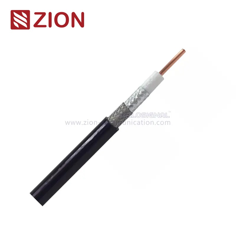
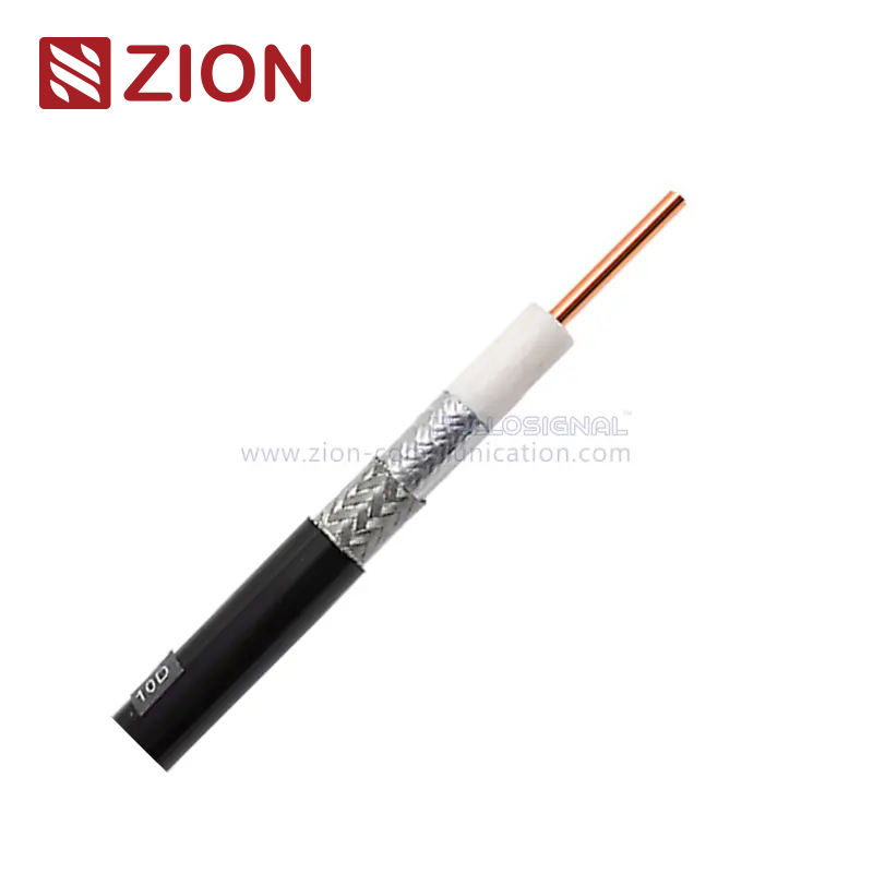
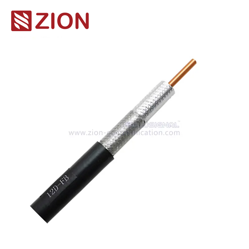
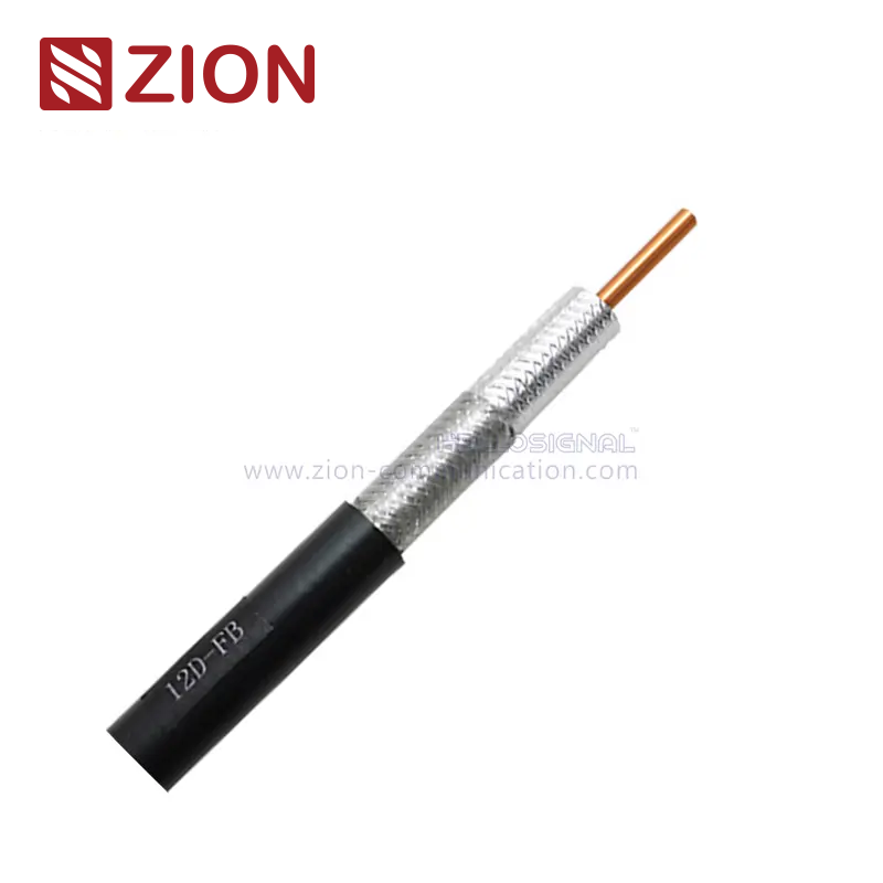
Each listed product uses a center conductor, foamed PE dielectric, bonded aluminum foil, tinned-copper braid, and black PE jacket. In practical terms, these layers carry the RF signal, maintain spacing and impedance, provide shielding, and protect the cable. Exact dimensions and electrical values vary by product code.
Inner conductor
Carries the RF signal. The range uses bare copper or CCA, with listed conductor diameters from 1.07 mm to 4.40 mm.
Foamed PE dielectric
Keeps the center conductor separated from the shield and is part of the cable's impedance and propagation design.
Foil and braid
Bonded aluminum foil and tinned-copper braid form the shielding system. Confirm shielding effectiveness and braid coverage for the exact code when they are project-critical.
Black PE jacket
Provides the outer protective layer. For exposed installations, specify the environment and request confirmation of UV, weather, temperature, and sealing requirements.
Where is D-FB coax cable used?
D-FB cable fits 50 ohm RF links where a flexible braided cable is needed between antennas, radio equipment, feeders, or equipment-room hardware. It is not a substitute for 75 ohm video coax, and the installation still needs a complete loss, connector, environmental, and mechanical check.
Antenna feeder links
Use the operating frequency, route length, and total link-loss allowance to select the cable. Include both cable and connector losses in the calculation.
Base stations
Separate long feeder sections from short equipment jumpers when that produces a more practical model mix. Confirm grounding, weatherproofing, supports, and termination hardware separately.
Paging and radio systems
D-FB models can be considered for 50 ohm radio communication links. State the exact band, power level, connector, and allowable insertion loss in the RFQ.
Equipment rooms
Compact sizes may simplify dense routing and maintenance access, provided they meet the loss target. Check bend clearance and connector service space before choosing a larger feeder size.
D-FB coax cable FAQ
The quickest way to avoid a wrong specification is to separate the cable family, size, conductor material, and project-specific electrical limits.
What is D-FB coax cable?
It is a 50 ohm RF coaxial cable family with foamed PE dielectric, foil-and-braid shielding, and multiple cable sizes. The family is used for wireless communication and feeder-related links where the selected product's loss and mechanical limits fit the system.
What is the difference between 3D-FB and 12D-FB?
The main verified differences are physical size and conductor diameter: 3D-FB uses a 1.07 mm conductor with a 5.40 mm jacket, while 12D-FB uses a 4.40 mm conductor with a 15.60 mm jacket. Compare attenuation at the actual frequency before treating either size as the right electrical choice.
Should I choose BC or CCA?
Choose the conductor material required by the project specification and verified electrical data. BC and CCA versions are separate product codes; compare DCR, attenuation, termination, compliance needs, and approved-material rules instead of assuming they are interchangeable.
Can D-FB cable be used for an outdoor antenna?
It can be considered for outdoor antenna feeder work when the selected PE-jacket version, temperature range, UV exposure, water sealing, grounding, and connector weatherproofing are confirmed for the site. Do not rely on the jacket material alone as a complete outdoor approval.
What information is needed to calculate the right size?
Provide frequency, route length, maximum cable loss, system impedance, connector pair, bend and routing constraints, environment, conductor preference, and quantity. These inputs allow a datasheet-based comparison instead of choosing by diameter alone.
What should I include in a D-FB cable RFQ?
A useful RFQ identifies the exact electrical and mechanical decision points. Include the following so the cable code, connector, and installation requirements can be checked together.
Required D-FB size or permission to recommend a size
Operating frequency or frequency range and system impedance
Route length and maximum allowable cable or assembly loss
Bare copper or CCA conductor requirement
Bulk cable or finished assembly, including both connector types and orientations
Indoor or outdoor environment, temperature range, UV, moisture, and sealing conditions
Routing limits: maximum cable diameter, bend space, tray or conduit, and support method
Quantity by model or route zone, requested length, packaging, marking, and test documentation





 Fiber Optic Cable
 Fiber Optic Tools
 Ethernet Cable
 Coaxial Cable
 Fire & Security Cable
 Voice, Audio & Video
 Power & Control Cable