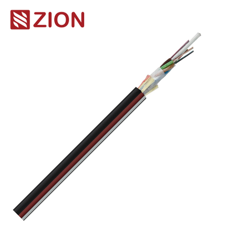


12/24/48 Core ADSS
ADSS Optical Fiber Cable
A broad ADSS family entry covering 12, 24 and 48-core options. Use it to compare span, sheath and accessory choices before fixing the exact construction.
View Product Details →ADSS cable is an all-dielectric, self-supporting fiber optic cable for aerial installation without a separate messenger wire. ZION ADSS options cover G.652.D single-mode designs, multiple fiber counts and span-specific versions. Choose by actual span and loading first, then confirm fiber count, PE or AT sheath, single or double jacket, sag and compatible fittings.
The series includes 12 product entries, ranging from low-count 6/8/12-core options to a 96-core, 80 m span model. Several entries group multiple fiber counts, while the 12F, 48F and 96F products provide fixed 80 m span configurations. Always confirm the exact mechanical design for the route rather than selecting from fiber count alone.
12/24/48 Core ADSS
A broad ADSS family entry covering 12, 24 and 48-core options. Use it to compare span, sheath and accessory choices before fixing the exact construction.
View Product Details →6/8/12 Core G.652.D
G.652.D single-mode cable with 6, 8 or 12 fibers and a listed maximum span of 200 m. Confirm the selected span design and site loading.
View Product Details →12/16/24 Core G.652.D
A G.652.D outdoor ADSS option in 12, 16 or 24-core versions. Confirm span, sheath and mechanical loading for the selected configuration.
View Product Details →18/24/36 Core G.652.D
Single-jacket PE cable with G.652.D fibers in 18, 24 or 36-core versions. Confirm span and the actual electrical environment before ordering.
View Product Details →24/32/48 Core G.652.D
G.652.D ADSS cable in 24, 32 or 48-core versions with a listed 50–200 m span range. Route loading still determines the final design.
View Product Details →30/40/60 Core G.652.D
Higher-count G.652.D ADSS cable with 30, 40 or 60 fibers and a listed 50–200 m span range. Confirm loading and sheath.
View Product Details →36/48/72 Core G.652.D
G.652.D ADSS cable in 36, 48 or 72-core versions for outdoor aerial deployment. Confirm span, sheath and electrical environment.
View Product Details →ADSS 12F / 80 m
A 12-core G.652.D single-mode, single-jacket ADSS cable identified for an 80 m span. Confirm actual route loads and fittings.
View Product Details →ADSS 48F / 80 m
A 48-core G.652.D single-mode ADSS cable identified for an 80 m span and aerial use. Confirm route loads and hardware.
View Product Details →ADSS 96F / 80 m
A 96-core G.652.D single-mode, single-jacket ADSS cable identified for an 80 m span. Confirm loading and attachment hardware.
View Product Details →24 Core ADSS
A focused 24-core ADSS option. Span length, fiber type, sheath and installation conditions determine the final specification and price.
View Product Details →ADSS Single Sheath
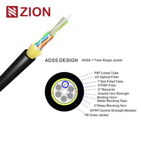
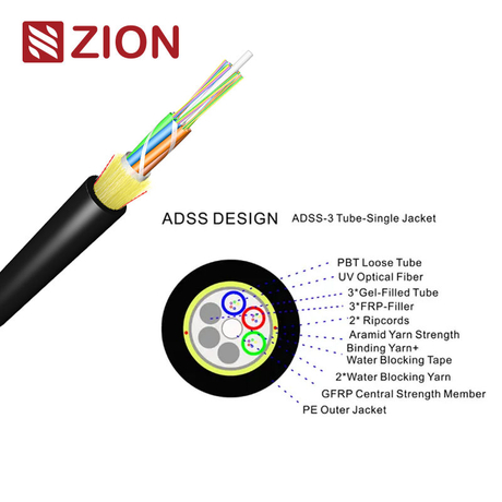
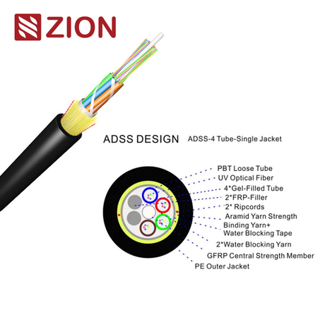
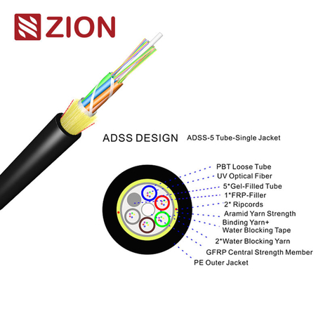
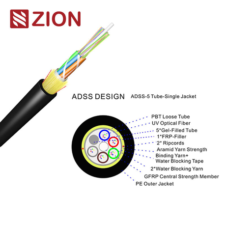
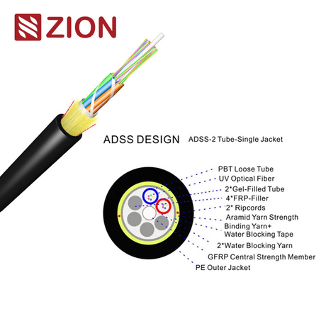
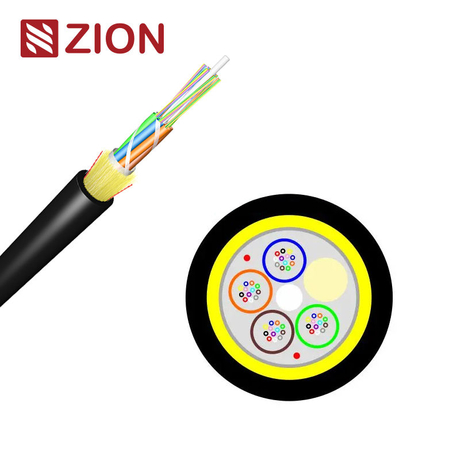
A single-sheath design with gel-filled loose tubes, a GFRP strength member and PE outer sheath. Confirm fiber count and mechanical values.
View Product Details →Start with the route, not the catalog code. Span, sag, wind, ice, temperature and the electrical environment determine the mechanical and sheath design; fiber count is selected after those constraints are understood.
Specify each pole-to-pole span and the governing maximum span. An “80 m” or “50–200 m” listing is a starting point, not approval for every route; sag, wind, ice and safety factors still matter.
Choose the active requirement plus practical spare capacity. Listed options run from 6 to 96 fibers, while the broader ADSS design range can require a project-specific confirmation for other counts.
PE is the ordinary polyethylene sheath; AT is an anti-tracking sheath for higher electrical stress. Do not choose from line voltage alone—provide the suspension-point electric-field assessment and confirm the sheath for that location.
Single-jacket products suit many standard aerial routes. A double-jacket design may be considered when the project requires greater mechanical protection or longer-span performance; confirm diameter, weight and fittings together.
Ask for RTS, MAT and EDS for the selected design. RTS is rated tensile strength, MAT is maximum allowable working tension, and EDS describes everyday operating stress; these values support sag-tension and vibration design.
Use fiber count and listed span to create a shortlist. The final cable still needs route-specific confirmation of sheath, diameter, weight, RTS, MAT, EDS, sag and fittings.
| Model | Fiber Count | Listed Span | Structure / Selection Note |
|---|---|---|---|
| ADSS 12/24/48 | 12 / 24 / 48 fibers | Confirm by version | Broad family entry for type, sheath and accessory selection |
| G.652.D 6/8/12 | 6 / 8 / 12 fibers | Up to 200 m listed | Low-count single-jacket option |
| G.652.D 12/16/24 | 12 / 16 / 24 fibers | Confirm by version | Outdoor single-mode ADSS |
| G.652.D 18/24/36 | 18 / 24 / 36 fibers | Confirm by version | Single-jacket PE design |
| G.652.D 24/32/48 | 24 / 32 / 48 fibers | 50–200 m listed | Single-jacket design |
| G.652.D 30/40/60 | 30 / 40 / 60 fibers | 50–200 m listed | PE-jacket higher-count option |
| G.652.D 36/48/72 | 36 / 48 / 72 fibers | Confirm by version | Higher-count single-jacket option |
| ADSS 12F | 12 fibers | 80 m | G.652.D, single-mode, single jacket |
| ADSS 48F | 48 fibers | 80 m | G.652.D, single-mode, aerial use |
| ADSS 96F | 96 fibers | 80 m | G.652.D, single-mode, single jacket |
| 24 Core ADSS | 24 fibers | Confirm by version | Project-specific span, sheath and fiber type |
| ADSS Single Sheath | Confirm by version | Confirm by version | Gel-filled loose tube, GFRP and PE outer sheath |
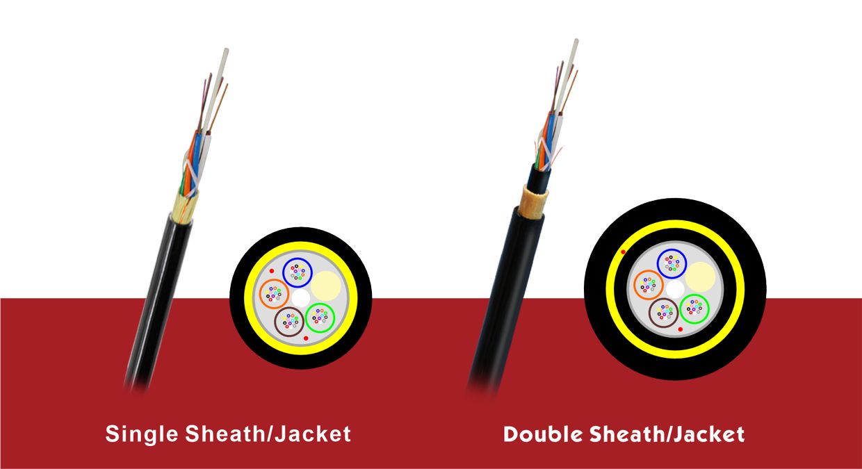
Choose the sheath construction by mechanical exposure, span design and support limitations. A second jacket can add protection, but it also increases cable diameter, weight and cost, so it should solve a defined route condition rather than be selected automatically.
A single outer jacket keeps the cable lighter and generally more economical. It fits routes with lower mechanical-damage risk where the selected design still provides the required UV, moisture and abrasion protection.
Inner and outer jackets provide greater mechanical and abrasion protection for harsher routes, vegetation or severe weather exposure. The added material increases weight and diameter, so pole loading and fittings must be rechecked.
ADSS design balances optical-fiber strain, aramid-yarn strength, cable weight, wind, ice, sag, span and electrical exposure. The ranges below are category-level references, not guaranteed values for every model; the selected product data sheet and route calculation govern the final design.
| Design Item | Category Reference | How to Use It |
|---|---|---|
| Fiber count | 4–144 fibers as a general design range | Listed product cards cover 6–96 fibers; confirm other counts as project-specific versions. |
| Outside diameter | Single jacket: 8–12 mm; double jacket: 12.5–18 mm | Use the exact model diameter to select clamps, storage hardware and minimum bend radius. |
| Cable weight | 200–250 kg/km for referenced 6/12/24/48/96-fiber designs | Do not use this range for pole loading; request the exact model value. |
| Tensile capacity | 4–50 kN as a broad design reference | Compare RTS, MAT and EDS from the exact data sheet with route loads. |
| Span capability | Designs may extend to 700 m | Long-span capability is project-specific and requires complete wind, ice, sag, terrain and safety-factor inputs. |
| Sheath environment | PE or anti-tracking AT | Confirm electric-field strength at the suspension point; nominal line voltage alone is not enough. |
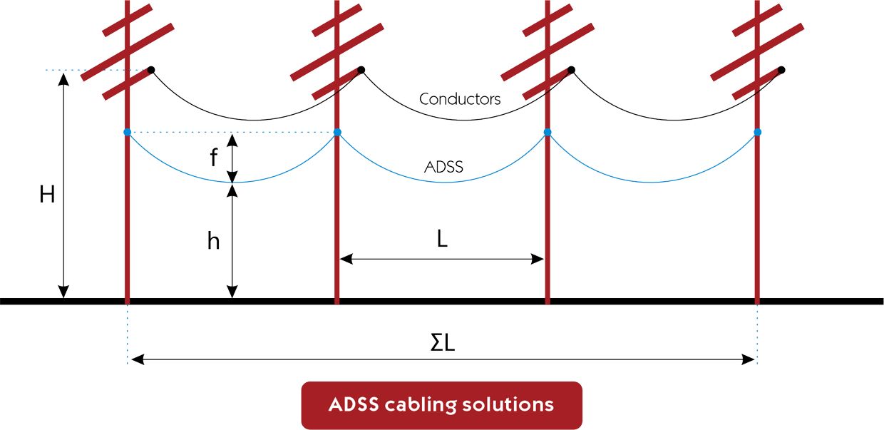
The maximum design load combines cable self-weight, ice load and wind load. Span and sag convert that distributed load into cable tension; terrain, temperature and unbalanced loading may add further cases.
Aramid yarn is the main tensile-strength component in common ADSS designs. Yarn grade, total cross-sectional area, lay pitch and angle are sized from the required strength and allowable fiber strain; request the calculation basis for long-span projects.
Loose-tube or ribbon construction provides controlled excess fiber length so the glass fibers remain at low strain. Repeaterless transmission distance is an optical link-budget question involving fiber attenuation, splices, connectors and active equipment—not a cable-only guarantee.
These tensile terms describe different load conditions, so they should not be treated as interchangeable. The percentages below are design references for this category; use the exact product data sheet and the project standard for acceptance.
Rated Tensile Strength is the calculated strength reference for the load-bearing section, primarily the aramid strength system. It is the base value used to express other tension limits.
Ultimate Tensile Strength describes short-duration overload capability. A category reference is greater than 60% of RTS, but the selected model and governing specification must define the actual acceptance value.
Maximum Allowable Tension is used in sag-tension-span analysis. A category reference is 40% of RTS; under MAT, the referenced fiber-strain limits are no more than 0.05% for laminated construction and 0.1% for central-tube construction without additional attenuation.
Everyday Strength represents long-term average operating stress and is used for fatigue and vibration design. A category reference is 16–25% of RTS, with no fiber strain or additional attenuation under the stated everyday condition.
ADSS is used for self-supporting aerial optical links where a non-metallic cable is preferred. It is not an electrical ground wire, and it should not be treated as interchangeable with OPGW or ordinary messenger-supported aerial cable.
ADSS can be installed on utility poles or towers for optical communication, but the attachment location and sheath must match the electric-field environment. It does not replace the ground-wire function of OPGW.
Self-supporting construction suits pole-to-pole telecom and access routes without a separate metallic messenger. Span, clearance, sag and attachment hardware must be engineered as one system.
ADSS can connect buildings or facilities across aerial routes where dielectric construction is useful. It is not intended for direct burial or duct installation unless a separate product specification explicitly permits that use.
Low- and mid-count ADSS options can serve rural aerial expansion, while higher-count models add capacity. Route survey data remains necessary even for apparently simple short spans.
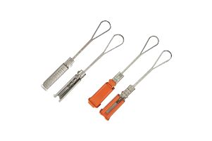
The main ADSS accessory set includes eight hardware types for anchoring, suspension, routing and service-loop management. Every item must match cable diameter, tensile rating, span and support arrangement; hardware selected only by appearance can concentrate stress or violate bend-radius requirements.
Anchors ADSS cable at terminations or major directional changes and distributes gripping force over a controlled cable length.
Uses a wedge mechanism for anchoring and adjustment. Confirm the approved cable-diameter and tension range before use.
Supports the cable at intermediate poles or towers while limiting local bending and compression at the support point.
Maintains cable position at tension points, route ends or sharper directional changes where the hardware must resist longitudinal load.
Attaches suspension, tension or routing hardware to a pole or tower. Confirm structural capacity, mounting-hole pattern, pole type and corrosion protection for the site.
Provides a connection or guiding point for compatible ADSS hardware on poles or towers. Confirm working load, interface dimensions and corrosion protection before selection.
Stores service loops for future splicing, repair or route adjustment while maintaining the required cable bend radius.
Guides cable down a pole or tower toward a splice closure or termination point and controls movement and bend radius.
ADSS means All-Dielectric Self-Supporting. In simple terms, the cable contains no metallic support member and is designed to support its own weight between aerial attachment points.
PE is a standard polyethylene sheath, while AT is an anti-tracking sheath intended for higher electrical stress. The correct choice depends on the electric field at the actual suspension point, not only the nominal line voltage.
No. Span is only one input; sag, wind, ice, temperature, cable weight, tensile limits, attachment height and safety factors also affect the design. Provide the full route conditions before confirming a model.
No. ADSS is a dielectric telecom cable attached separately to poles or towers; OPGW is an optical ground wire that is part of the transmission-line grounding system.
The fitting set depends on cable diameter, span, tension and support arrangement. Confirm suspension clamps, tension assemblies, vibration protection and any pole or tower hardware against the selected cable data sheet.
You do not need to calculate the final cable design before requesting a quote. Provide the route data below so the proposed ADSS construction and fittings can be checked together.
Fiber type, fiber count and required spare capacity
Nominal span, maximum span, route length, pole or tower arrangement and attachment height
Wind speed, ice thickness, temperature range, sag and clearance requirements
Power-line voltage and electric-field data at the suspension point
PE or AT sheath preference and single- or double-jacket requirement
Required RTS, MAT, EDS, cable diameter, weight and bend radius
Suspension, tension and vibration-control fittings
Drum length, quantity, printing, packaging, test reports and delivery documents
Certification and compliance references for project review, qualification and purchasing documentation.
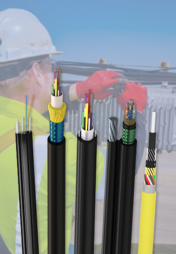 Fiber Optic CableAccess and backbone
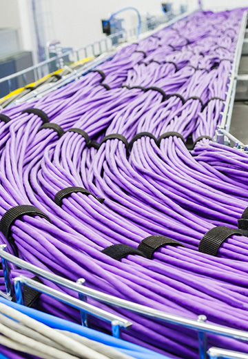
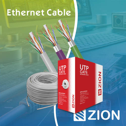 Ethernet CableCat5e to Cat8
 Coaxial CableRF and video signal
 Fire, Security & AlarmSafety systems
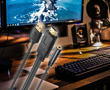 Voice, Audio & VideoSignal cabling
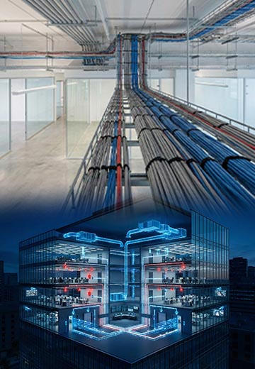 Power & Control CableEnergy and control
Outdoor, indoor, FTTH and distribution cable lines for access networks, backbone routes and campus deployments.
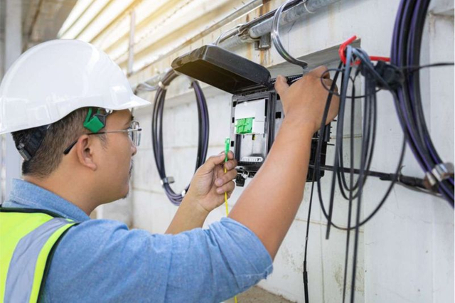 Telecom & ISP NetworksFTTH, PON, ODN
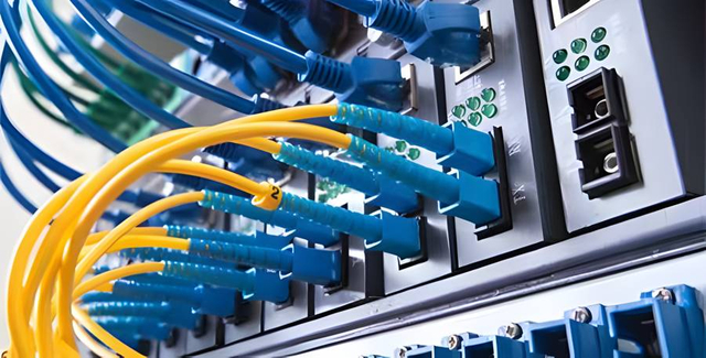 Data Center InfrastructureServer room cabling
 Building Low-Voltage SystemsBMS, AV, weak current
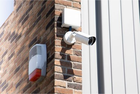 Security & Fire ProtectionAlarm, CCTV, access
 Industrial Automation CablePLC, RS485, fieldbus
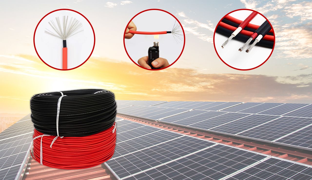 Energy & Power InfrastructureSolar, battery, power
For FTTH / PON access, outdoor fiber deployment, aerial routes, duct routes, direct burial routes, rural broadband and ODN planning.
Use calculators and planning tools for conduit capacity, PoE voltage drop and fiber optic link loss budget work.
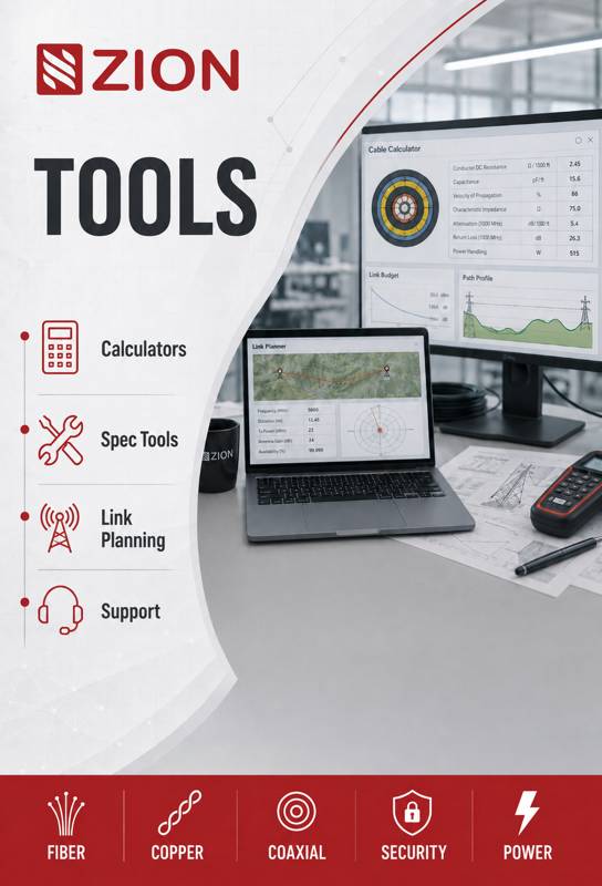







 Fiber Optic Tools